Optimization of the slewing ring bolt fatigue calculation
Ensuring safety in heavy machinery requires absolute precision. That is why the slewing ring bolt fatigue calculation is a critical process in the design of joints for large-dimension bearings. A poorly calculated joint can lead to costly downtimes or serious accidents.
At Atreydes Engineering, we address the challenge of validating hardware for demanding cyclic loads. Our goal is to ensure that each component supports the expected life cycle without unforeseen failures.
Tecma Drive S.L., a benchmark in the sector, needed a reliable method to establish the graphs of their hardware. They required analyzing qualities 8.8, 10.9, and 12.9 in the moment-axial load curves (M-Ra).
To respond to this need, we have developed a custom solution. It is a dynamic spreadsheet. This tool adapts to the M-Ra curves of the bearings in the client’s catalog.
Furthermore, it sets the limits for different hardware qualities. All this is done respecting rigorous static criteria and the essential slewing ring bolt fatigue calculation.
It is assumed that the joints exceed the limits if the most stressed bolt fails. Therefore, the calculations focus on the compliance of this critical bolt. This is vital in joints subjected to moments, where the stress depends on the distance to the axis.
Step 1: Methodology for slewing ring bolt fatigue calculation
For the slewing ring bolt fatigue calculation, we estimate the fatigue limit according to our handbook. We take 0.33 as the stress concentration factor ( k_f ).
Bolts present stress concentrations in the head and thread. This factor is usually 3 for rolled bolts and 3.8 for machined ones. However, this concentration does not decisively influence static loads. This is because the yield strength is usually not exceeded.
In contrast, in fatigue analysis, the situation changes. Since it is a physical rupture calculation, the yield strength is locally exceeded. Here is where stress concentrators are determinant.
For this slewing ring bolt fatigue calculation, we use a concentration value of 3. This is because most are produced by cold rolling. You can check our Mechanical Simulation Services for more info.
k_f = \Large \frac{1}{3} \normalsize = 0.33
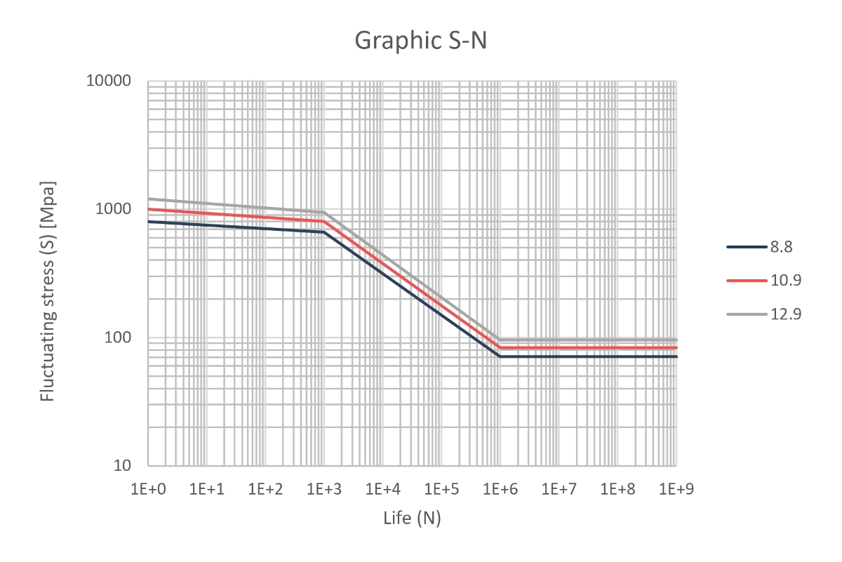
Once the infinite life limits (> 10^6 cycles) are established, we extrapolate the value for fewer cycles under alternating loads.
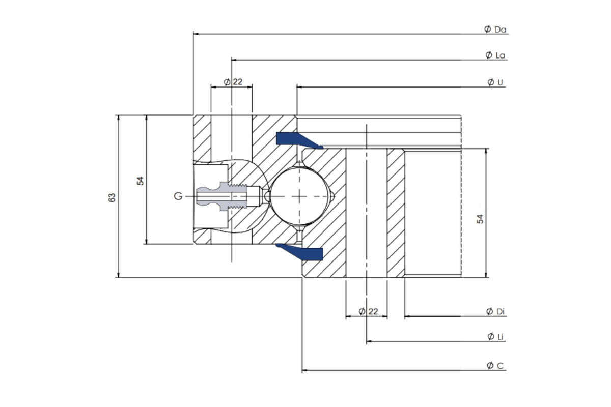
Loads Considered
To correctly execute the slewing ring bolt fatigue calculation, we have considered the following loads:
- Alternating Moment ( M ) on the ring. This causes mean and alternating traction due to cyclic forces.
- Constant Axial Compression Load ( R_a ). This derives from the self-weight supported by the bearing. It produces compression stresses lower than the traction of the moment.
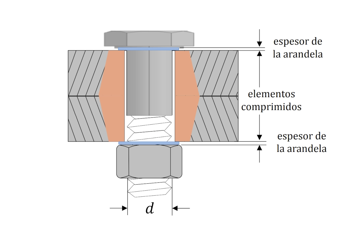
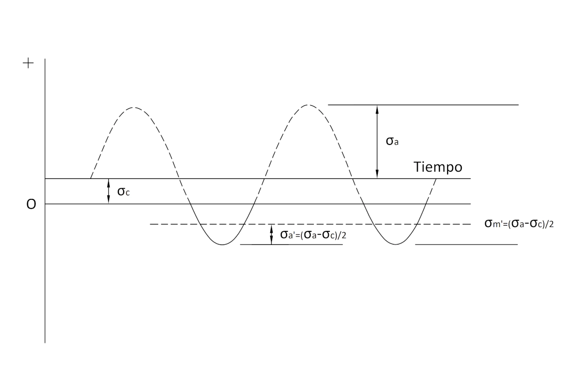
Bolts only work in traction. Therefore, they only support mean ( \sigma'_m ) and alternating ( \sigma'_a ) stresses of this type.
For this state of loads, the traction stresses in the joint are defined as:
\sigma'_a = \sigma'_m = \Large \frac{\sigma_a - \sigma_c}{2} \normalsize, for \sigma_a > \sigma_c
Where:
- \sigma_a : alternating stress due to moment.
- \sigma_c : compression stress due to axial load.
Although we study all combinations, this is the most relevant for Tecma Drive S.L.
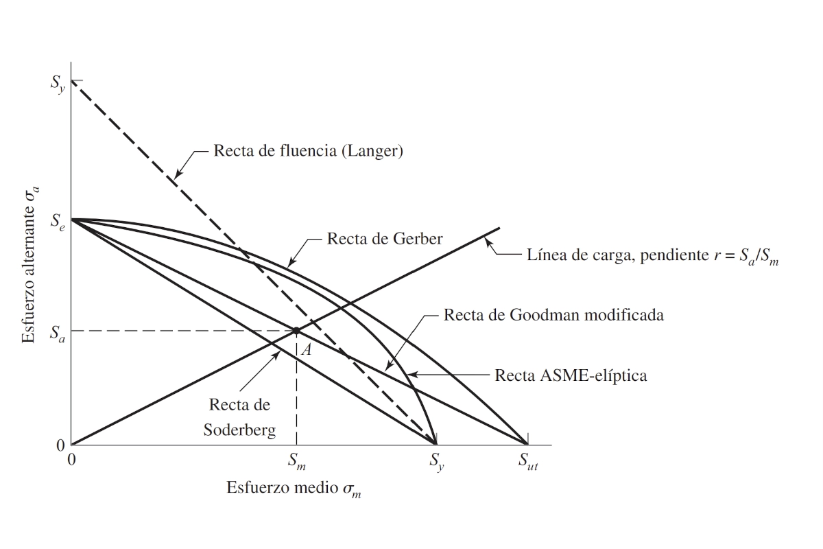
Applied Fatigue Criteria
There are several recognized criteria for the slewing ring bolt fatigue calculation:
- Soderberg Criterio
- Modified Goodman Criterion
- Gerber Criterion
- ASME-elliptic Criterion
The detailed equations are in our handbook on Fluctuating Stresses. For this project, we chose the Soderberg criterion. It is the most restrictive and places us on the safe side:
\Large \frac{\sigma'_a}{S_e} \normalsize + \Large \frac{\sigma'_m}{S_y} \normalsize = 1
Knowing that:
\sigma'_a = \sigma'_m = \Large \frac{\sigma_a - \sigma_c}{2}
\sigma_a \Large \frac{4 M}{n \phi A_s}
\sigma_c \Large \frac{R_a}{n A_s}
Substituting stresses for loads in the Soderberg equation:
\sigma_a = \Large \frac{2 S_e S_y}{S_e + S_y} \normalsize + \sigma_c
\Large \frac{4M}{n \phi A_s} = \Large \frac{2 S_e S_y}{S_e + S_y} \normalsize + \Large \frac{R_a}{n A_s}
Rearranging, we obtain the limit line for the hardware analysis:
M = M* + \Large \frac{\phi}{4} \normalsize R_a
Where:
M* = M_{Sod} = \Large \frac{n \phi A_s S_e S_y}{2(S_e + S_y)}
This indicates the alternating failure moment at infinite life with zero axial load.
We can adapt this line to other criteria by replacing the moment M* :
M_{ASME-Elliptic} = \Large \frac{n \phi A_s S_e S_y}{2 \sqrt{(S_e + S_y)}}
M_{Goodman} = \Large \frac{n \phi A_s S_e S_{ut}}{2(S_e + S_{ut})}
M_{Gerber} = \Large \frac{1}{4} \normalsize n \phi A_s S^2_{ut} \left(- \Large \frac{1}{S_e} \normalsize + \Large \sqrt( \frac{1}{S^2_e} \normalsize + \Large \frac{4}{S^2_{ut}}) \right)
Variables used:
- n : number of bolts.
- \phi : position diameter.
- A_s : resistant section.
- S_e : fatigue limit.
- S_{ut} : ultimate tensile strength.
S_y : yield strength.
In addition to the slewing ring bolt fatigue calculation, it is imperative to verify static loads. According to Eurocode 3, there are two main checks:
1. Slip calculation (Category C).
2. Tension calculation (Category E).
Step2: Slip Resistance
The design slip resistance ( F_{s,RD} ) is defined as follows:
F_{s,Rd} = \Large \frac{k_s n \mu (F_{p,C} - 0.8 F_{t,Ed})}{\gamma_{M3}}
Where:
- k_s : hole parameter (1 for standard).
- n : slip planes (1 for bearings).
- \mu : friction coefficient.
- F_{p,C} : preloading force.
F_{p,C} = 0.7 S_{ut} A_s
The axial tensile force ( F_{t,Ed} ) for the most stressed bolt is:
F_{t,Ed} = \Large \frac{4M}{n \phi} \normalsize + \Large \frac{R_a}{n}
This detail is complementary to the slewing ring bolt fatigue calculation and ensures the integrity of the flange. The coefficient \gamma_{M3} is 1.25. The joint complies if:
\Large \frac {F_{s,Rd}} {F_{v,Ed}} \normalsize = \Large \frac {n F_{s,Rd}} {R_v} \normalsize > 1
With R_v being the shear force.
Step 3: Tension Resistance
The tension resistance ( F_{t,Rd} ) according to the standard is:
F_{t,Rd} = \Large \frac {k_2 S_{ut} A_s} {\gamma_{M2}}
The joint resists tension if the following relationship is met:
\Large \frac{F_{t,Rd}}{F_{t,Ed}} \normalsize = \Large \frac{n F_{t,Rd}}{R_a} \normalsize >1
With R_a as the axial tensile stress.
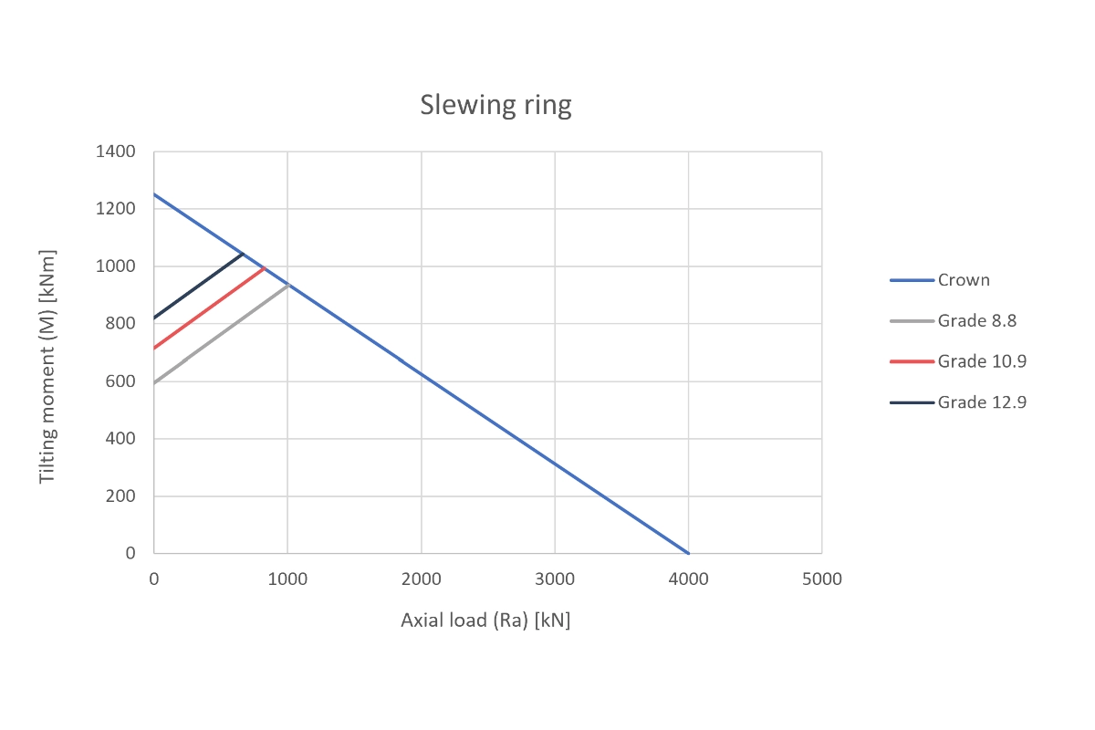
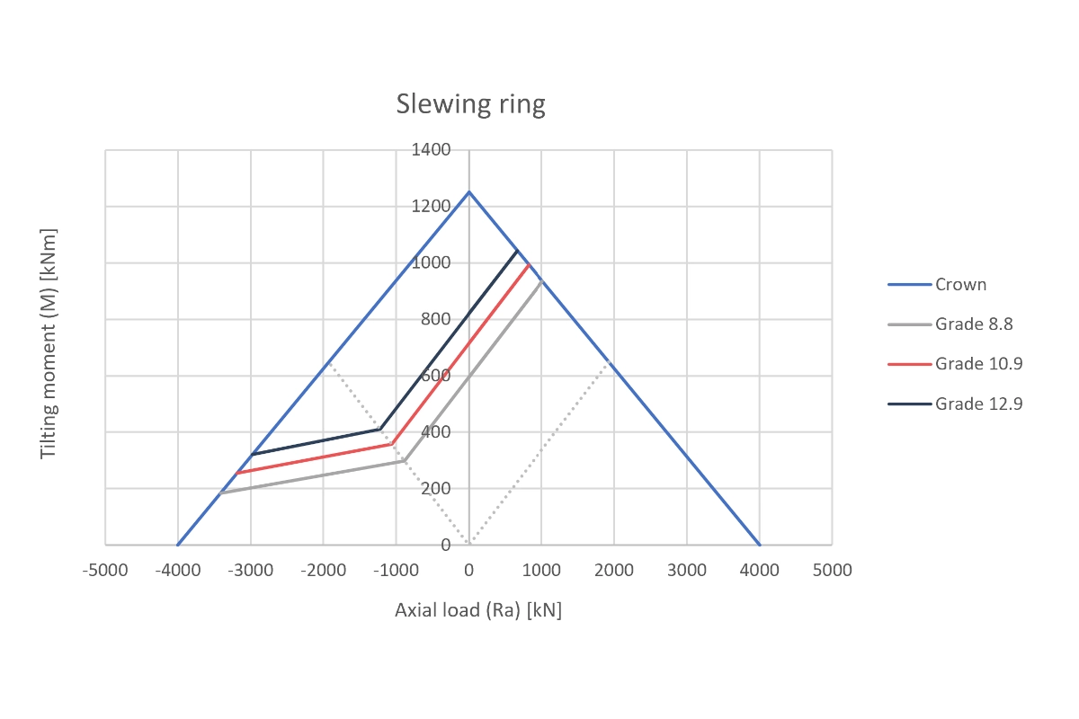
Study Results
We have analyzed hardware of qualities 8.8, 10.9, and 12.9. The study covers both static loads and the complex slewing ring bolt fatigue calculation for large bearings.
The Excel tool developed automates these procedures. It allows framing the results directly in the M-Ra graphs of Tecma Drive S.L. Below, we show the behavior of the bolts under combined tension and compression.
These results validate our focus on advanced mechanical calculation. If you need to optimize your joints or validate critical designs, you can consult other success stories in our Project Portfolio.
Do you need help with a complex joint? Contact Atreydes Engineering and ensure the reliability of your equipment.