Suction Sail Design
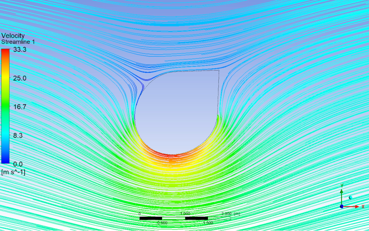
In the 1980s, Jacques Cousteau developed several patents on the suction sail. This autonomous device allows the propulsion of ships using wind energy. The main idea relies on aspirating the air flow. This flow detaches in the wake of a cylindrical structure towards its interior. By doing this, the boundary layer detachment is effectively avoided.
According to these patents, the lift force increases significantly. It grows about 6 times compared to a body without aspiration. Directing this force toward the direction of travel propels the ship forward. Therefore, an intelligent control system becomes strictly necessary. At Atreydes Engineering, we analyze these advanced systems to optimize modern navigation.
This technology was developed on the famous Alcyone ship. Its design has remained unchanged for decades. The rise of fossil fuels paused these innovations back then. Today, new environmental demands are completely changing the rules. A new international legislation forces a reduction in fuel consumption.
Because of this, the suction sail makes great sense again. It represents a clean alternative against greenhouse gas emissions. You can discover other similar technological milestones in our Projects Portfolio. There, we detail our innovative applications for the maritime sector.
Amazing principles of the suction sail
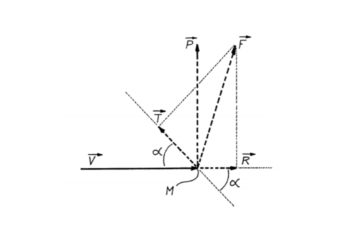
It all starts when the suction sail faces a fluid. Air moves at a relative velocity v . This generates an aerodynamic force, called F .
This force is divided into two main components. First, a lift force P , perpendicular to the velocity. Second, a drag force R , directed in the same direction as the air velocity.
Suppose the device moves forming an angle \alpha . This angle interacts with the velocity v . The system is subjected to a traction force T . This effort exactly corresponds to the projection of F on the direction of advance.
Traction increases as lift becomes higher. In turn, drag must be as small as possible. Both drag and lift are expressed by dimensionless coefficients.
C_d=\Large\frac{R}{\frac{1}{2}\rho V^2S}
C_l=\Large\frac{P}{\frac{1}{2}\rho V^2S}
Where:
- Cd: drag coefficient
- Cl: lift coefficient
- R: drag force
- ρ: air density
- P: lift force
- V: wind velocity
- S: surface exposed to the wind
Considering these mathematical expressions, the traction force T is defined as follows:
T=\frac{1}{2}\rho V^2S(C_l\cdot\sin\alpha-C_d\cdot\cos\alpha)
This mathematical formula demonstrates a vital aspect of the design. For a given velocity, the thrust depends on the product of the area ( S ) and the lift coefficient ( C_l ). If you wish to implement this technology, we can calculate all these exact parameters for your vessel. You can learn more about this in our Design and Simulation Engineering Service.
<blockquote>“Invention patent 507.586. Improvements in a high lift force device to use the energy of moving fluids especially for ship wind propulsion. Fondation Cousteau. 11/30/1981”</blockquote>
Key aspects of the system
The design of a suction sail integrates aerodynamics, mechanics, and automatic control. Prioritizing some areas over others generates highly difficult problems. In extreme cases, it makes the design technically impossible to solve.
All systems must be addressed in parallel working closely together. This is how we successfully meet the strict scope, time, and cost requirements. At Atreydes Engineering, we apply this comprehensive methodology for your project. Please, feel free to contact us.
A heavy suction sail makes no practical sense. Its own weight would subtract force from the wind impulse. Optimization requires manufacturing the entire structure in aluminum. This aluminum must be fully protected against marine salinity. We use specialized paint according to current marine standards.
Building the structure requires welding this specific material. Welding aluminum is more complicated than welding standard steel. Therefore, using benches and robotic welding will ensure quality. The low weight of aluminum will greatly reduce inertial forces. This directly favors the system’s own stability and structural resistance.
Cousteau proposed an elliptical design for the suction sail section. He positioned a rear mobile flap to stabilize the output flow. This flap changed to a symmetrical position depending on the wind. He established an optimal angle of attack of 20º. At this exact point, the profile reached its maximum lift coefficient.
Increasing this angle forces an increase in the aspiration flow. There comes a time when the flow cannot adhere. Or, the necessary flow is so large that it becomes unfeasible. This required flow is greater as the incident wind gets stronger. Thus, Cousteau limited his design to maximum winds of 10 m/s.
The elliptical shape on the Alcyone has exact measurements. It has a primary axis of 2.05 m and a secondary of 1.35 m. Its calculated eccentricity is strictly 0.66. This geometry allows installing a large axial fan inside.
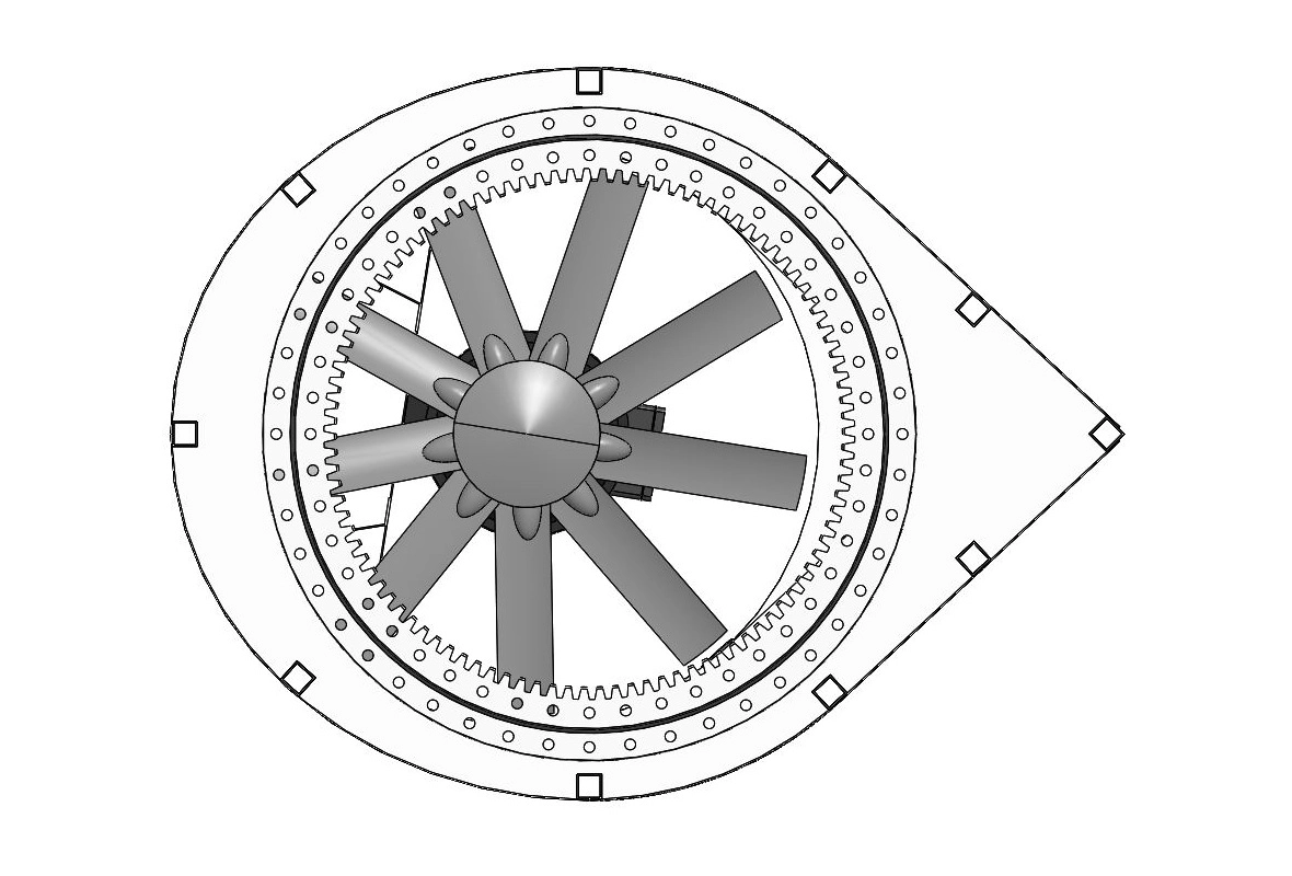
This fan uses a 1250 mm diameter propeller. It can provide a maximum aspiration flow of 100,000 m3/h. This equals a maximum flow of 34 kg/s for a 10-meter height. Today, this geometry is rapidly optimized using advanced CFD analysis.
Currently, there are two ways to characterize a body’s aerodynamic behavior. We can use wind tunnel tests or digital CFD simulations. When analyzing a suction sail, the Reynolds number must be adjusted. The internal flow of the profile must match the external flow perfectly.
When testing physical scale models, a great practical problem arises. Aspiration holes are already small at full real scale. In the model, they are reduced to just a few millimeters. They are very difficult to manipulate and clog quite easily. This severely distorts the final aerodynamic test results. This method is too slow to optimize geometries properly.
CFD simulations constitute a much faster and accurate tool. They allow creating alternative geometries and testing different design options. Results are obtained very quickly compared to the wind tunnel. Due to the real complication of the aspiration flow, it is the best method.
The aerodynamic profile must show the same geometry on both sides. When the wind changes, the flap and surface positions must swap. Cousteau proposed a suction sail with two independent aspiration zones. One of them is sealed by the flap depending on the wind attack.
This raises two strongly coupled mechanical problems to solve. The first is that the flap must rotate to adapt to the wind. The second, and most important, is sealing the inactive zone. If part of the flow is lost, the boundary layer will not adhere. We would require more flow, but fan capacity is limited.
Also, the flap must move with external components connected to the structure. Being outdoors, it will withstand inertial and severe wind loads. It will introduce additional loads on the guiding mechanisms themselves. It must also guarantee perfect sealing using anti-corrosion marine joints.
Current solutions propose leaving the flap completely fixed to the structure. Thus, assembly is greatly simplified to better withstand inertial loads. This also facilitates the delicate automatic control system design. The economic savings in mechanisms and rotation motors is very considerable.
In return, we must modify the geometry to optimize the lift coefficient. This coefficient decreases by about 10% compared to Cousteau’s design. It also implies an increase in the required absorbed flow. This will translate into increasing the fan diameter, which is acceptable.
In CFD simulations, we use a boundary condition for flow adherence. It is defined as a mass flow of air entering the surface. In reality, this demands a true internal and external pressure difference. This depression is achieved by installing a fan that moves the air.
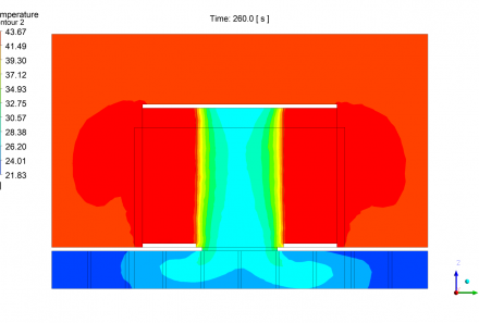
Cousteau placed this fan at the very top of the profile. Air enters through small drilled circular holes on the surface. However, the pressure distribution is not constant along the suction sail. Therefore, the flow absorbed through each hole will be quite different. Air will pass more where it finds greater external pressure.
Looking at the static pressure graphs, the physical behavior is clear. The flow will be lower in the holes far from the flap. Conversely, it will increase in the holes very close to it. The only thing that remains constant is the fan power.
We need high flows to absorb the wake at medium-high pressures. Axial fans are the absolute best option compared to radial ones. The latter provide very high depressions but at extremely low flows. Axial fans rotate to achieve a great depression downstream.
The moved flow depends heavily on the radius of the blades. The achieved depression depends on the number and angle of these blades. The pressure drops of the system must be carefully considered. If we have the fan at the top, losses will be higher at the bottom.
The pressure drop across the perforated grid is extremely critical. It will be greater the smaller the designed hole diameter is. If the hole is too small, the fan will not provide the necessary depression. We will have to operate at a lower wind speed to compensate. Another solution is testing at a representative full scale to determine exact losses.
Related posts