International Context
The PV structure calculation in Slovakia detailed here responds to a specific offer for Eucomsa (Cox-Abengoa Group). To guarantee the technical and economic viability of the project, we have based the analysis on 5 fundamental keys:
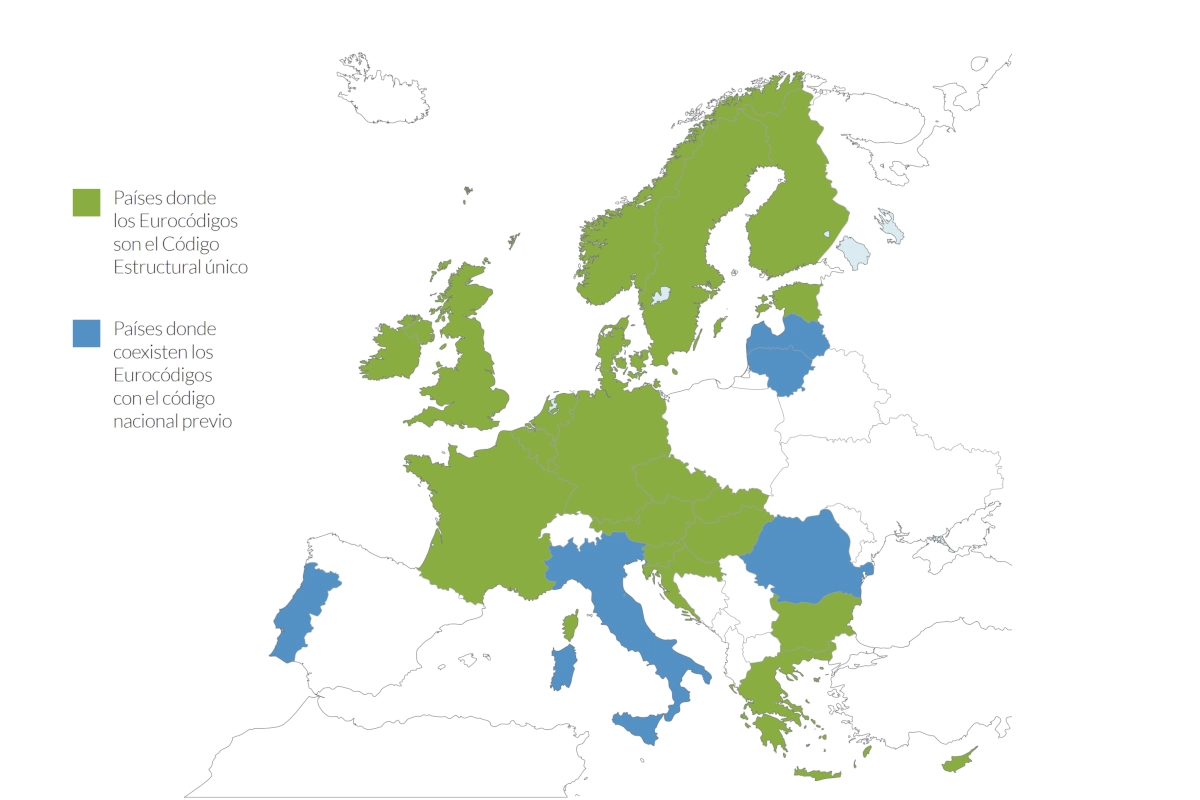
- Local Regulations. We ensured strict adaptation to the Eurocode and its Slovak national annexes.
- Efficient Geometry. We proposed a design of “Y” frames to reduce the number of foundations.
- Critical Loads. We paid special attention to the snow overload (1.09 kN/m²), which is determinant in the area.
- Materials. We focused on cost optimization by combining S275 and S235 steel.
- Safety. We performed seismic validation and rigid node checks complying with all Ultimate Limit States (U.L.S.).
The main objective has been to design a metal support capable of resisting the specific climatic loads of the Zilina area. At Atreydes Engineering, we apply current regulations to secure your investment.
Design for the PV structure calculation in Slovakia
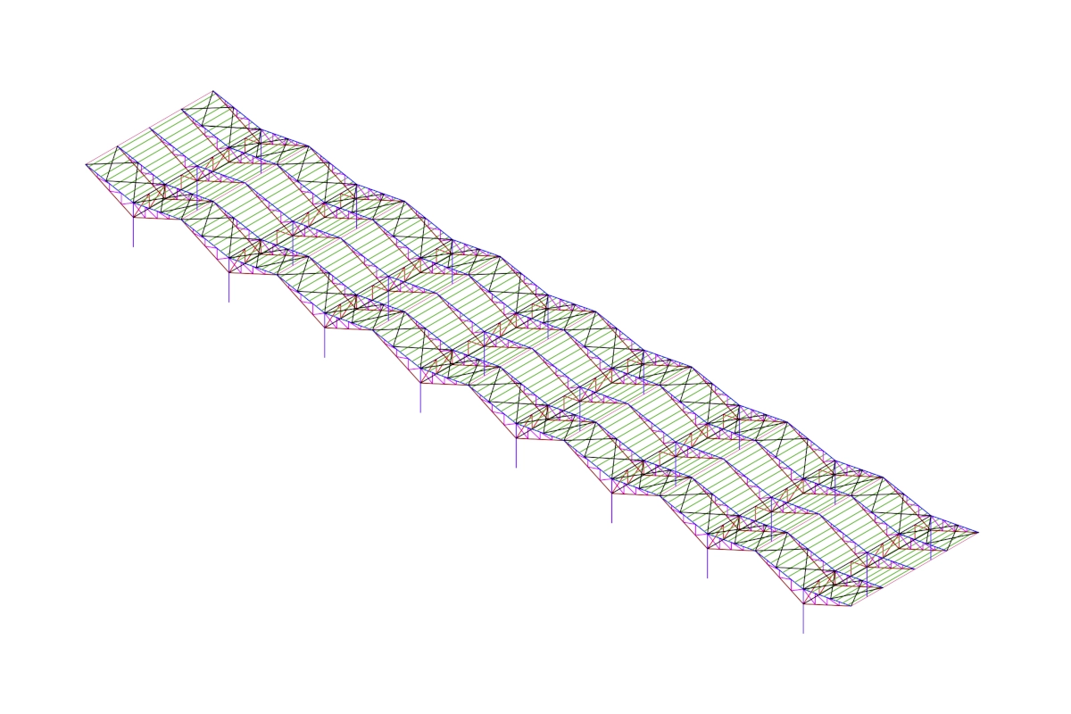
The geometry chosen for the PV structure calculation in Slovakia responds to the need to optimize steel and assembly. The plant consists of 5 lines with 8 “Y” shaped frames.
To gain diaphanous space, the even frames lack pillars. Instead, they are supported by transverse trusses on the odd ones. This solution significantly reduces the number of foundations required.
Geometric characteristics defined in the project:
- Wings: 7.5m in length inclined at 11º.
- Height: 4m free height up to the truss.
- Profiling: Trusses with a maximum depth of 2m.
You can see similar optimization solutions in our Project Portfolio.
Material Selection
To refine the PV structure calculation in Slovakia, we have differentiated between exterior frames (more exposed to wind) and interior ones.
Materials used in the analysis:
- Steel S275: Used for rolled profiles.
- Steel S235: Used for cold-formed profiles.


Climatic Load Analysis
The design for the PV structure calculation in Slovakia considers all Eurocode hypotheses. We analyzed self-weight, dead load of panels, wind, snow, and seismic activity.
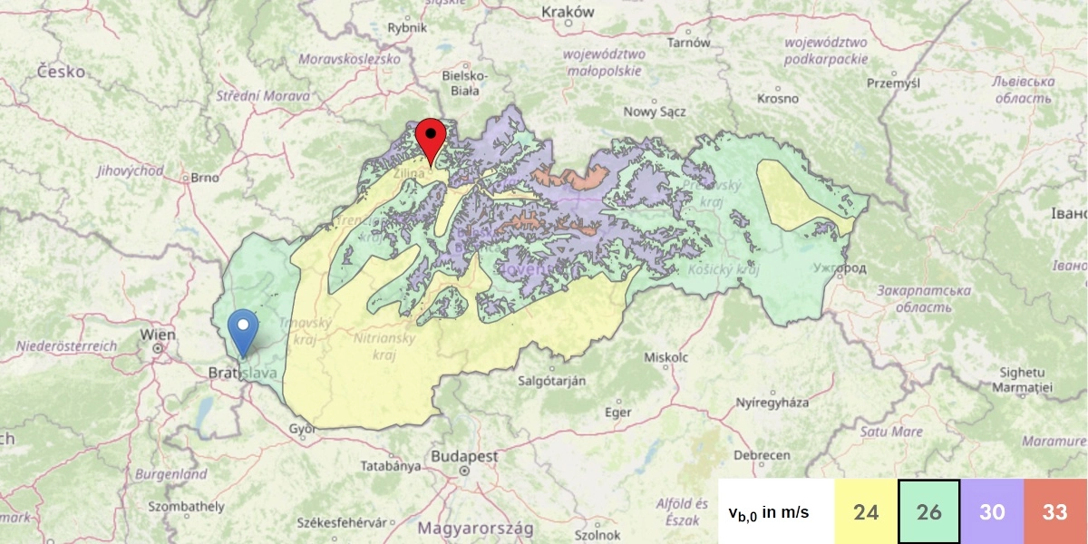
Design Wind Speed
The basic wind speed ( v_b ) in the area is 24 m/s. The dynamic pressure ( q_{ref} ) is obtained considering an air density of 1.25 kg/m³.
q_{ref} = \large \frac{1}{2} \normalsize \rho v_b^2
Pressure Coefficients
For a structure of 7.5m in type II terrain, the exposure coefficient C_e (z) is 2.17.
We apply the canopy pressure coefficients C_p for duo-pitch roofs. These are corrected by obstruction factors, which are essential in the PV structure calculation in Slovakia.


Critical Load in Central Europe
The snow load ( s_k ) is 1.09 kN/m². This value is determinant in the PV structure calculation in Slovakia and is increased by shape coefficients ( \mu ).
With an inclination of 11º, we use \mu_1 = 0.8 and \mu_3 = 1.09 . This generates a trapezoidal overload of up to 1.192 N/m² in accumulation zones.


Seismic Action
For the location of this project, the basic acceleration is 0.63 m/s² (0.06 g). Although it is moderate, its analysis is mandatory in any rigorous PV structure calculation in Slovakia.
We have generated the elastic design spectrum to verify ductility and stability. This follows the standard of our Structural Calculation services.


Panel Weight
We consider a unit weight of 30 kg per module as a general specification. This is standard in the PV structure calculation in Slovakia for this region. The nominal load is 150 N/m².
This load is distributed among the Z-type purlins, each supporting approximately 0.15 kN/m.
Analysis Results
Regulatory Verification
The model generated for the PV structure calculation in Slovakia complies with all Ultimate Limit States (U.L.S.).
Allowable stresses are not exceeded, and global stability is not compromised. The analyzed vibration modes ensure correct dynamic behavior of the structure.


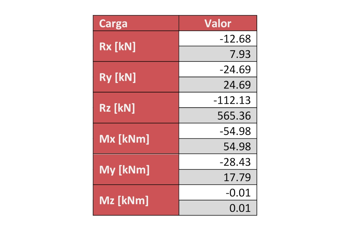
Envelope for Foundations
We provide the factored loads per pillar. This data allows for the accurate dimensioning of footings or piles.
Technical Note: These values must be combined with the local geotechnical study for the final foundation design.
The PV structure calculation in Slovakia must be complemented with these types of studies to guarantee structural stability.
Project Conclusions
This project validates the safety of the proposed design. The PV structure calculation in Slovakia requires special attention to snow and wind, factors that this structure withstands comfortably according to Eurocode.
Final Recommendations:
- Haunching: Execute rigid nodes at the base of the pillars.
- Stiffness: Reinforce the pillar-truss connection to avoid excessive translational movement.
Do you need to optimize your international photovoltaic project? Contact Atreydes Engineering for expert advice.