Gears

Gears

In this section, we will define the geometry required to achieve motion between spur gears with parallel axes. We will not go into the calculation as it depends on considerations that would take a lot of literature such as tooth bending, surface durability or gear fatigue.

Geometría

In gear design, we find 3+1 fundamental parameters, on which the other design parameters depend: the number of gear teeth (z), the pitch diameter (d), which is the circumference equivalent to the contact, through which the gear rolls without slipping, and the module (m), which establishes a tooth size index in the International System units and which is usually tabulated in millimeters.
Module
Preferred1, 1.25, 1.5, 2, 2.5, 3, 4, 5, 6, 8, 10, 12, 16, 20, 25, 32, 40, 50
Next Choise1.125, 1.375, 1,75, 2.25, 3.5, 4.5, 5.5, 7, 9, 11, 14, 18, 22, 28, 36, 45
The interaction of these three parameters provides the fundamental gear equation and defines the gear geometry.

  \large d = m \cdot z

The fourth parameter is the pressure angle (φ) which is equivalent to the angle between the direction of contact force and the direction of speed in the driven gear. In modern gear construction, the value of 20° has been adopted, although for special applications the value of 14.5º is also used.
Engranajes parámetros 3
Parameters
Pitch (p) is the distance measured on the primitive circumference between homologous points of two consecutive teeth. The pitch is equal to the sum of the tooth thickness and the gap between consecutive teeth.

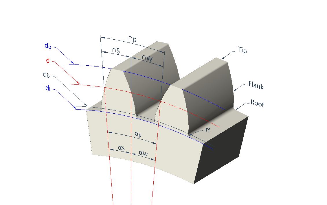
  \normalsize p = \Large \frac{\pi d}{z}

Tooth thickness (S): tooth thickness measured on the pitch diameter.

  \normalsize S = p  \Large \frac {19}{40}

Tooth gap: (W): space between tooth and tooth measured on the pitch diameter.

  \normalsize W = p  \Large \frac {21}{40}

Pitch angle (αp) is the angle of the pitch with respect to the center of the gear unit.

  \normalsize \alpha_p (º) = \Large \frac{2 p}{d} \frac{180}{\pi}

Tooth thickness angle (αS): angle which cover the thickness of the tooth with respect to the gear center.

  \normalsize \alpha_S (º) = \Large \frac{2 S}{d} \frac{180}{\pi}

Tooth gap angle (αW): angle which covers the tooth gap with respect to the gear center.

  \normalsize \alpha_W (º) = \Large \frac{2 W}{d} \frac{180}{\pi}

Base diameter (db): diameter at which the involute of the tooth flank begins.

  \normalsize d_b = d  cos(\phi)

Outer diameter (de): diameter where the crest of the tooth is located.

  \normalsize d_e = d +2m

Inner diameter (di): diameter where the root of the tooth is located.

  \normalsize d_i = d -2.5m

Root radius (rf): radius between the tooth and inner diameter.

  \normalsize r_f \approx 0.25m

Tooth length (l): distance from the root to the tip of the tooth.

  \normalsize l = \frac {1}{2}(d_e-d_i)

Gearing Condition

"Two gears mesh if they have the same module."

\large m_1 = m_2 

Gear Ratio

Mathematically, gear ratio can be expressed in multiple ways, according to the following expressions:

r_t = \Large \frac {\omega_2}{\omega_1} \normalsize = \Large \frac {d_1}{d_2} \normalsize = \Large \frac {z_1}{z_2}  

Where ω is the angular velocity of each gear, with d and z already defined as the pitch diameter and number of teeth respectively.

Contact Ratio

The contact ratio (ε) is a parameter which measures the average number of teeth that are always in contact. As a general rule, ε should be greater than 1.2. This will ensure a greater capacity of the gear to transmit higher loads, provide greater stiffness to the transmission, while achieving a more uniform and less noisy operation.

\varepsilon = \Large \frac {L \tiny AB}{p  cos (\phi)} \normalsize> 1.2

Geometry of the parameters is shown below.
Longitud de contacto 2
Contact ratio
The contact line (LAB) can be calculated as the distance from point A to point B, d(A,B).

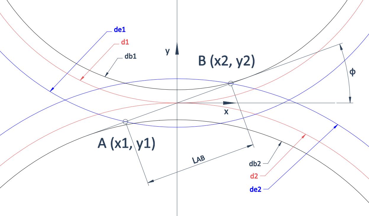
  L \tiny AB \normalsize = d(A,B) = \sqrt{(x_2-x_1)^2 + (y_2-y_1)^2}

The points A(x1, y1) and B(x2, y2) can be calculated as the intersection of the contact line (LAB) with the outer circumferences of each gear unit.
  x_1 = \Large \frac{db_1 tan(\phi) - \sqrt{ (1+tan^2(\phi)) (db_1+2m)^2-db_1^2}}{2(1+tan^2(\phi))} 
  y_1 = tan(\phi)  x_1   
  x_2 = \Large \frac{- db_2 tan(\phi) + \sqrt{ (1+tan^2(\phi)) (db_2+2m)^2-db_2^2}}{2(1+tan^2(\phi))} 
  y_2 = tan(\phi)  x_2   

Interference

The interference occurs when the tip of the driven tooth contacts the flank of the driving tooth. In this case the flank of the driving tooth first makes contact with the driven tooth before the involute portion of the driving tooth comes within range. In other words, contact is occurring below the base circle of gear on the noninvolute portion of the flank. The actual effect is that the involute tip or face of the driven gear tends to dig out the noninvolute flank of the driver.
When gear teeth are produced by a generation process, interference is automatically eliminated because the cutting tool removes the interfering portion of the flank. This effect is called undercutting; if undercutting is at all pronounced, the undercut tooth is considerably weakened. Thus, the effect of eliminating interference by a generation process is merely to substitute another problem for the original one.
The smallest number of teeth on a spur pinion and gear,1 one-to-one gear ratio, which can exist without interference is ZP1. This number of teeth for spur gears is given by:

Z_{P1} = \Large \frac{2(k)}{3sin^2(\phi)} \normalsize (1+\sqrt{1+3sin^2(\phi)}) = 12.3 = 13 teeth

where k is equal to 1 for full depth teeth and 0.8 for short teeth.
If the gear ratio between the pair of gears is greater than 1 equal to n, the smallest pinion that can mesh without interference will be:

Z_{Pn} = \Large \frac{2(k)}{(1+2n) sin^2(\phi)} \normalsize (n+\sqrt{n^2+(1+2n) sin^2(\phi)}) 

The largest gear (Zge) for a pinion with a specified number of teeth (Zpe), which is free of interference is:

Z_{ge} = \Large \frac{Z_{pe}^2 sin^2(\phi)-4k^2}{4k-2Z_{pe}sin^2(\phi)}   

nZpnZgn
11313
21530
31545
41664
61696
717119
77171309
78181404
90181620
100181800
ZpeZge
104
117
1210
1316
1426
1545
16101
171309
18No limit
The smallest spur pinion that will operate with a rack without interference is:

Z_{Pr} = \Large \frac{2(k)}{sin^2(\phi)} \normalsize = 17.1 = 18 teeth
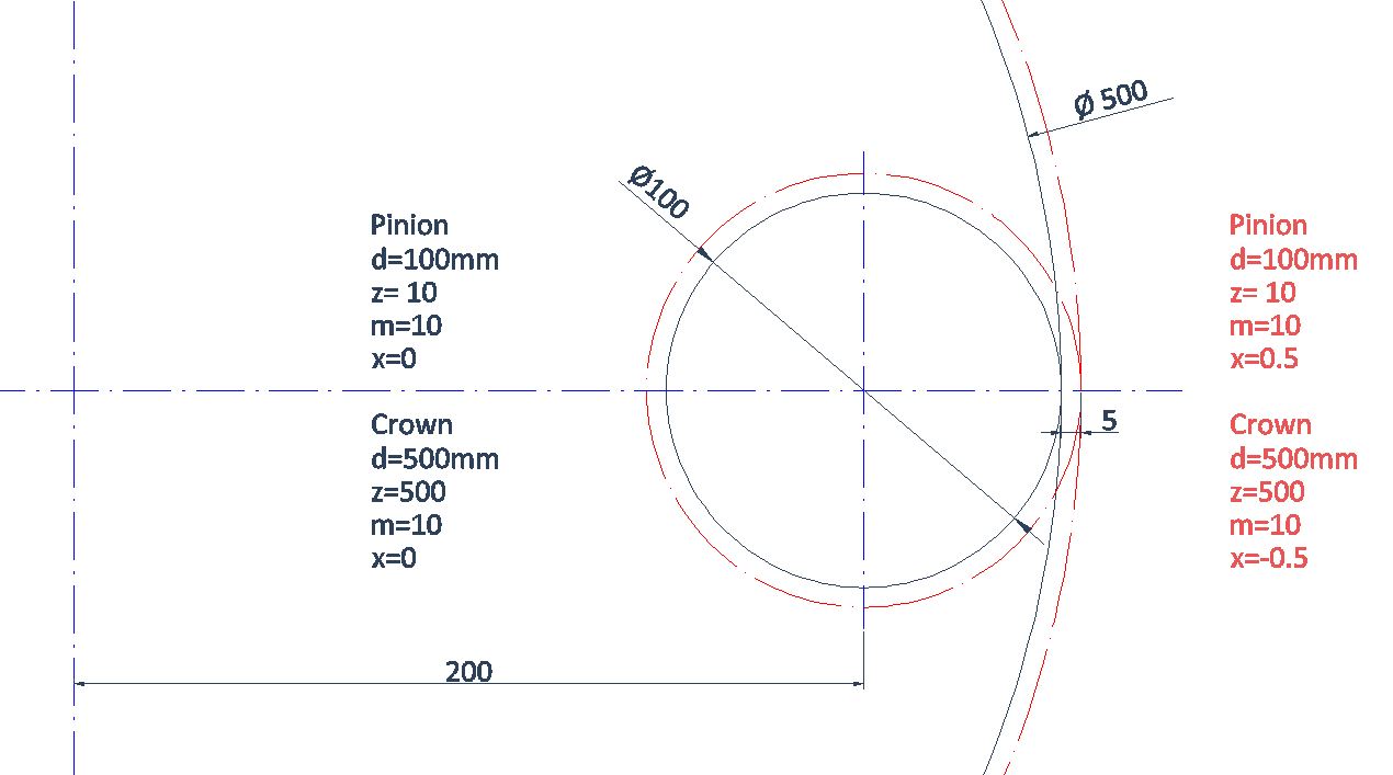
Since gear-shaping tools amount to contact with a rack, and the gear-hobbing process is similar, the minimum number of teeth to prevent interference to prevent undercutting by the hobbing process is equal to the value of ZPr. The importance of the problem of teeth that have been weakened by undercutting cannot be overemphasized.

Shifted Gears

Para evitar To avoid this tooth root undercutting in gears with interference, the teeth are usually modified by means of a parameter called modification (x), whose sign is positive for external gears and negative for internal gears. This increases the root of the tooth, avoiding the undercutting.
A positive sign of x indicates a backward movement of the tool to machine the gear while a negative sign indicates a forward movement to create the gear.
Because this operation achieves much sharper teeth a second parameter called truncation (k) trims them to a diameter smaller than the outer diameter. The value of k is always negative.
Once modification (x) and truncation (k) come into play, the gear geometry is modified as follows:
shifted gear 2
Comparison between ordinary and shifted gears [m=10, z=10, x=0.5]
External gears (x>0)
S' = S +2 m x tan (\phi)   
W' = W +2 m x tan (\phi)   
d_e' = d_e +2 m x + 2 m k 
d_i' = d_i +2 m x 
Internal gears (x<0)
S' = S - 2 m x tan (\phi)   
W' = W - 2 m x tan (\phi)   
d_e' = d_e - 2 m x - 2 m k
d_i' = d_i - 2 m x 
Although these gears still have their primitive diameter to fulfill with the fundamental gear equation, for practical purposes it is as if they were modified to (d’):

d' = d + 2 m x      for external gears

d' = d - 2 m x      for internal gears
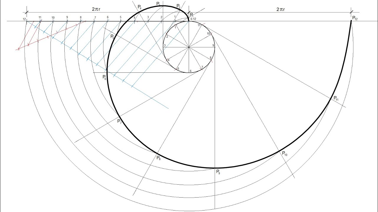
shifted gear
Shifted pitch diameters

Involute

The teeth of spur gears have an involute profile because it guarantees a constant transmission ratio without slippage and optimum power transmission between the gears, since, at the point of contact between two teeth, the tangent to the profile is common to both teeth.
Involute is a flat curve of development, whose normals are tangents of the circumference. This circumference in a gear is defined by the base diameter (db).
When drawing an involute, the parametric equations are the easiest to handle:

x (t) = \Large \frac{d_b}{2} \normalsize (cos (t) + t sin(t)) 

y (t) = \Large \frac{d_b}{2} \normalsize (sin (t) - t cos(t)) 

The radius serves us as a reference to choose the parameter t, since the end of the involute is marked by the outer diameter (de).

r (t) = \sqrt{x^2 (t) + y^2(t)} 

evolvente
Involute curve