Simply supported beam with symmetric overhangs
Reactions
F_1 = F_2 = \Large \frac{qL}{2}
Shear Force
V(x) = \begin{cases} -qx & \text{for} x \le \large \frac{L-s}{2} \\ -q(x-\Large \frac{L}{2}\normalsize) & \text{for} \large \frac{L-s}{2} \normalsize < x \le \small L-\large \frac{L-s}{2} \\ -q(x+L) & \text{for} x > \small L-\large \frac{L-s}{2} \end{cases}
-V_A = V_D = \Large \frac{q (L-s)}{2}
V_B = -V_C = \Large \frac{qs}{2}
Bending Moments
M(x) = \begin{cases} -\large \frac{1}{2} \normalsize qx^2 & \text{for} x \le \large \frac{L-s}{2} \\ -\large \frac{1}{2} \normalsize q(x^2-Lx+L\Large\frac{L-s}{2}\normalsize) & \text{for} \large \frac{L-s}{2} \normalsize < x \le \small L-\large \frac{L-s}{2} \\ -\large \frac{1}{2} \normalsize q(x^2-2Lx+L^2) & \text{for} x > \small L-\large \frac{L-s}{2} \end{cases}
M_E = M_I = -\Large \frac{1}{8}\normalsize qL(L-s); \text{for} x = \large \frac{L-s}{2} \normalsize = \small L- \large \frac{L-s}{2}
M_G = \Large \frac{1}{2} \normalsize qL \Large (\frac{Ls}{2} \normalsize - \Large \frac{L^2}{4}) \normalsize; \text{for} x = \large \frac{L}{2}
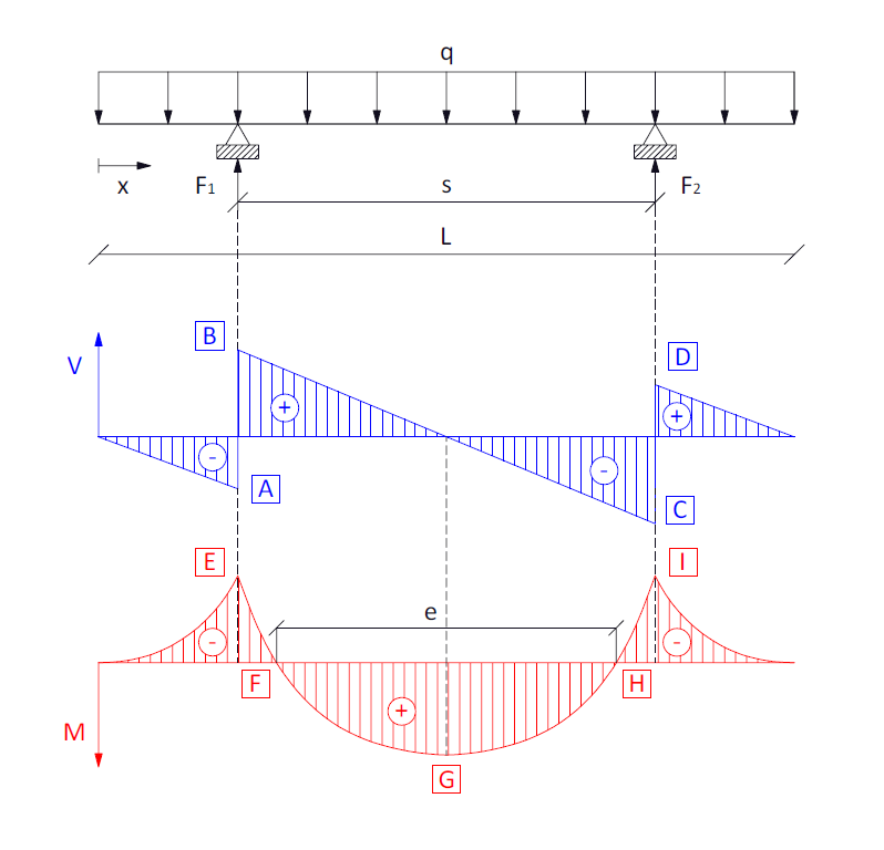
It can be shown that the relationship between L and s that minimizes bending moments, i.e., -M_E = M_G , is:
s =f(L) : -M_E = M_G
s = \Large \frac{2}{2+\sqrt{2}} \normalsize L
The distance e that marks the separation between zero moments at points F and H of the central span is:
e = \sqrt{2Ls-L^2}
Where:
M_F = M_H = 0
x_F = \Large \frac{L-e}{2}
x_H = \Large \frac{L+e}{2}
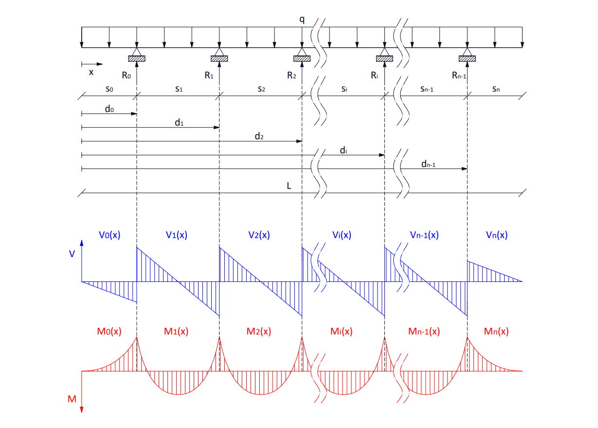
Continuous beam with overhangs
Characterization of a continuous beam under a distributed load with n sections, 2 symmetric overhangs, n-2 interior spans, and n-1 reactions.
L = d_n = \sum_{i=0}^{n} s_i
d_k = \sum_{i=0}^{k} s_i
Reactions
Since this is a statically indeterminate problem, as an approximation, it is assumed that each reaction supports half the load of each adjacent span, except for the reactions next to the overhangs, which will support the total overhang load plus half of the adjacent span load.
R_i(x) = \begin{cases} q(s_0+ \Large \frac{s_1}{2}\normalsize) & \text{for} i = 0 \\ q(\Large \frac{s_i+s_{i+1}}{2}\normalsize) & \text{for} i \in [1, n-2] \in \mathbb{N} \\ q(\Large \frac{s_{n-1}}{2}\normalsize +s_n) & \text{for} i = n-1 \end{cases}
Shear Force
The subscript k denotes the calculation section.
k = \begin{cases} 0 & \text{for left overhang} \\ \in [1, n-1] \in \mathbb{N} & \text{for interior spans} \\ n & \text{for right overhang} \end{cases}
V_k(x) = \begin{cases} -qx & \text{for} k = 0 \\ -qx+\sum_{i=0}^{k-1} R_i & \text{for} k \in [1, n-1] \in \mathbb{N} \\ -q(x+L) & \text{for} k = n \end{cases}
Bending Moments
M_k(x) = \begin{cases} -\large \frac{1}{2} \normalsize qx^2 & \text{for} k = 0 \\ -\large \frac{1}{2} \normalsize qx^2+x\sum_{i=0}^{k-1} R_i - \sum_{i=0}^{k-1} R_i d_i & \text{for} k \in [1, n-1] \in \mathbb{N} \\ -\large \frac{1}{2} \normalsize q(x^2-2Lx+L^2) & \text{for} k = n \end{cases}
The maximum moment occurring at the center of each span can be calculated as:
M_k(x_k) = -\large \frac{1}{2} \normalsize qx_k^2+x_k\sum_{i=0}^{k-1} R_i - \sum_{i=0}^{k-1} R_i d_i
Where:
x_k = d_k - \Large \frac{s_k}{2}
Does your structure have complex geometries or dynamic loads?
These simplified formulas are valid for pre-sizing and standard cases; they have limits.
At Atreydes Engineering, we validate non-linear cases in critical structures, complex joints, or fatigue using Finite Element Analysis (FEA) to ensure optimization and safety.