Bolted Circular Flange
In engineering, it is very common to find a circular flange fixed with bolts subjected to a bending moment. This is the case for pipe joints or plates supporting a bearing for rotating movements.
If there is a moment centered with the flange, since the joint bolts are at different distances from the axis of application of said moment, each will support a different tensile force. Therefore, it is necessary to determine these loads to properly dimension the bolted joint.
To begin with, the bolts furthest from the moment axis will support a maximum load (Fmax), which we will simply call F, while the bolts crossing the moment axis will have zero tensile load.
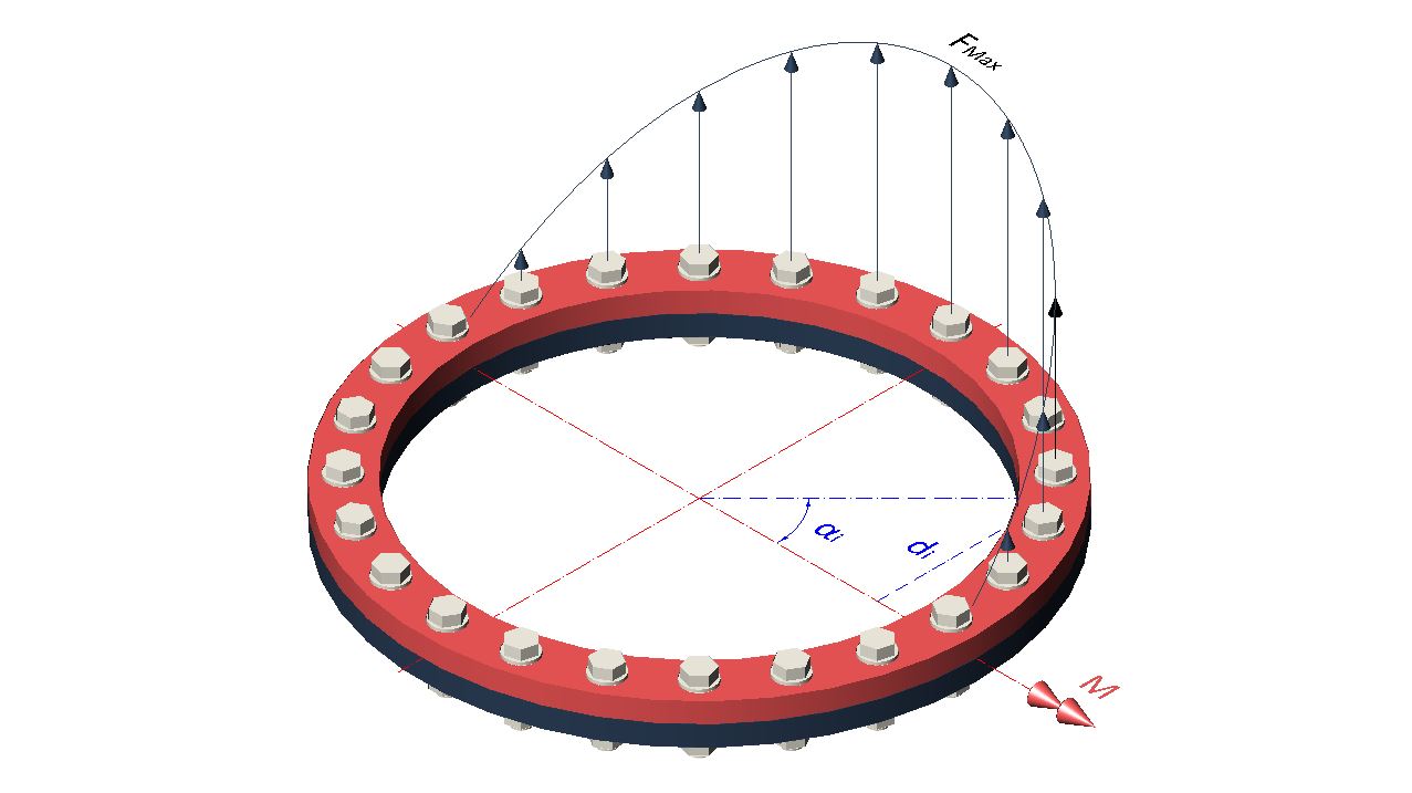
The load on the other bolts between these two positions depends linearly on their distance to the moment axis, if we look at the flange profile, but their contribution to the moment depends circularly on the position they occupy on the flange circumference.
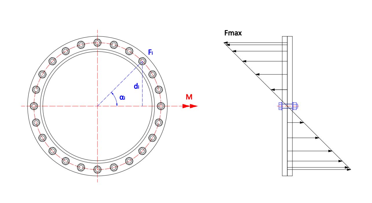
\normalsize d_i = R sin (\alpha_i)
\Large \frac {F}{R} = \frac {F_i}{d_i}
\normalsize M = \sum_{i=0}^n F sin (\alpha_i) \cdot R sin (\alpha_i) = F R \sum_{i=0}^n sin^2 (\alpha_i) = \Large \frac {F R n} {2}
\normalsize F_i = F sin (\alpha_i)
F = \Large \frac {2 M} {n R}
\normalsize F_i = F sin (\alpha_i) = \Large \frac {2 M} {n R} \normalsize sin (\alpha_i)
Beyond Static Formulas: Real-world Application
The theoretical formula F = \Large \frac {2 M} {n R} provides a solid basis for static pre-sizing. However, in critical heavy machinery, relying solely on static calculations is a risk.
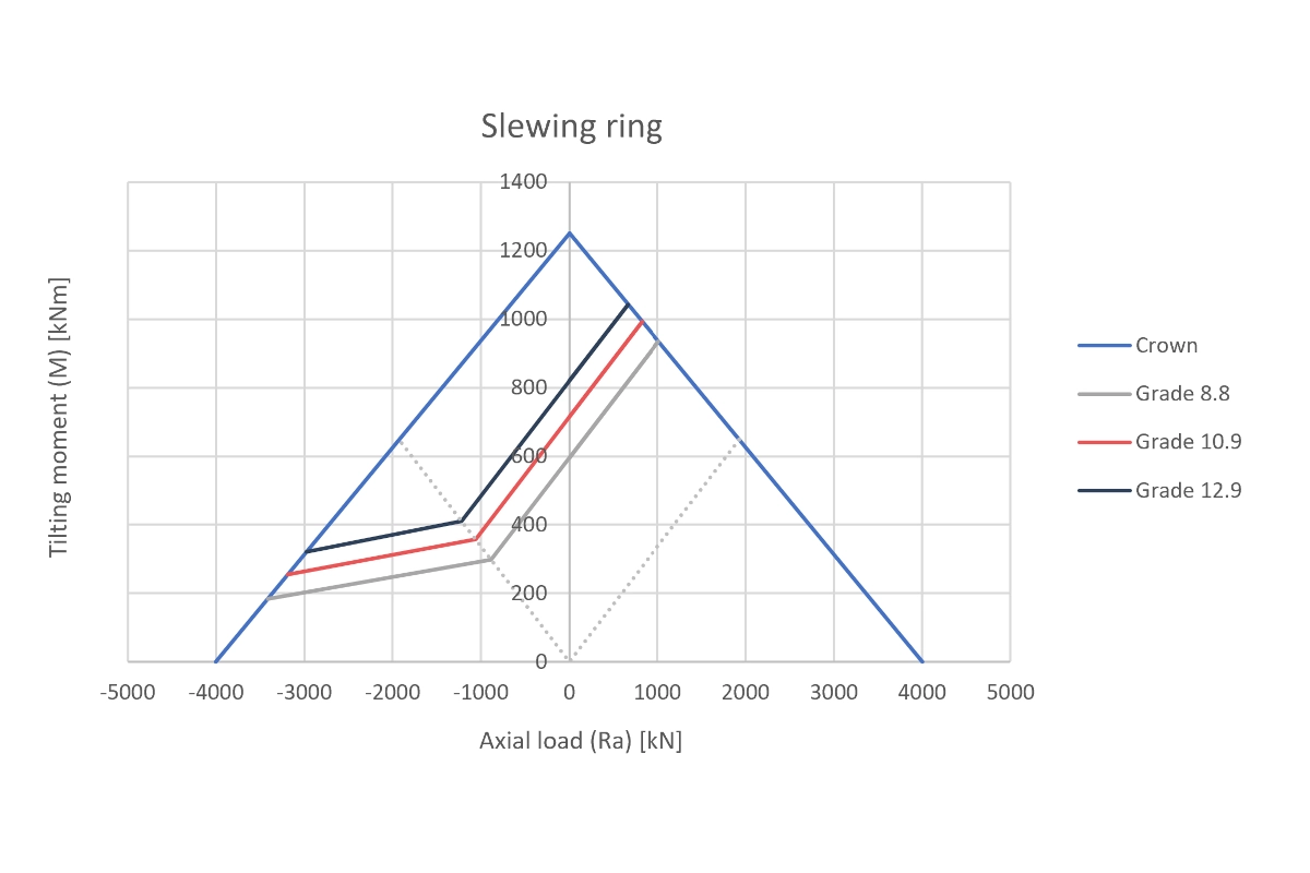
Case Study: Fatigue in Slewing Rings (Tecma Drive)
We tackled a complex challenge for Tecma Drive S.L.: validating fatigue life of fasteners in large slewing bearings (a massive circular flange application).
Using the Soderberg Criterion and custom M-Ra Curves (Moment vs. Axial Load), we analyzed grades 8.8, 10.9, and 12.9 to ensure safety under cyclic loads, preventing catastrophic failure in rotating equipment.