General Information
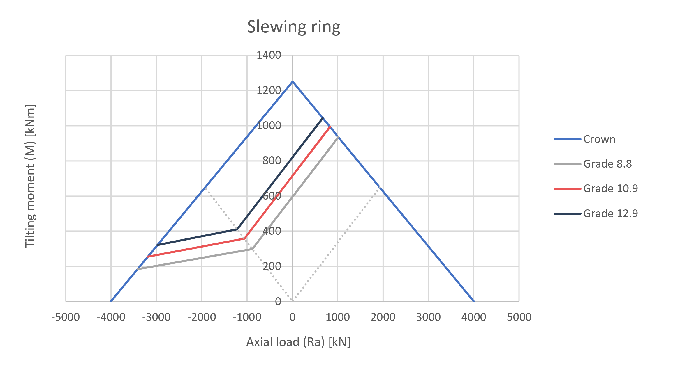
Tecma Drive S.L., a reference in slewing rings of large dimensions, needs a calculation method to establish the graphs of grades 8.8, 10.9 and 12.9 for bolts in the moment-axial load curves (M-Ra) of its catalog. From Atreydes Ingeniería, we have developed a dynamic Excel spreadsheet that adapts limits of different fastener grades to the M-Ra curves of slewing rings in the Tecma Drive S.L. catalog.
Calculation
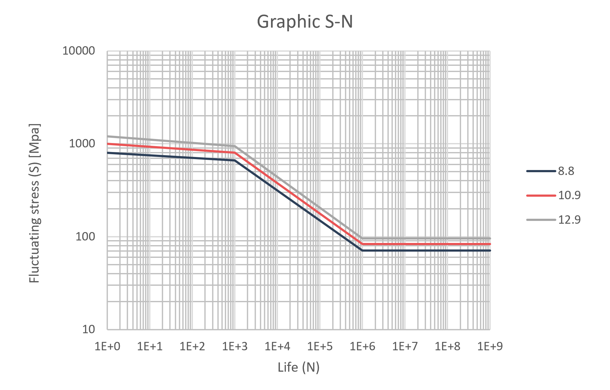
To calculate the material fatigue limit, we will use our handbook Fatigue in the section Estimation of the fatigue limit, taking the stress concentration factor ( k_f ) as 0.33.
It is known that bolts have stress concentrations in the bolt head and in the thread when it meets the nut. This stress concentration factor is 3 for rolled bolts and 3.8 for machined bolts.
This stress concentration does not influence static loads because it does not tend to exceed the elastic limit. In fatigue, and since it is a calculation procedure at the physical rupture of the element, the yield limit has to be exceeded for failure to occur, so stress concentrators start to come into play.
For bolts calculation, a stress concentrator value of 3 will be used since most bolts are mass produced by a cold rolling process being very rarely machined since this manufacturing process is more expensive.
k_f = \Large \frac{1}{3} \normalsize = 0.33
Once the fatigue limit at infinite life (> 10^6 ciclos) have been established, this value is extrapolated for a smaller number of cycles for purely alternating loads.
Loads
The following assumptions have been taken into account for the fatigue calculation:
- Alternating moment ( M ) in the slewing ring crown causing an average (sigma m) and alternating (sigma a) tensile load on the bolt, due to the application of cyclic external forces.
- A constant axial compressive load ( R_a ) mainly due to the self-weight of the elements supported by the slewing ring and which produces compressive stresses on the bearing bolts that are lower than the tensile stresses of the alternating moment.
Since the bolts only work in tensile conditions, they only support average tensile stresses ( \sigma'_m ) and alternating tensile stresses ( \sigma'_a ).
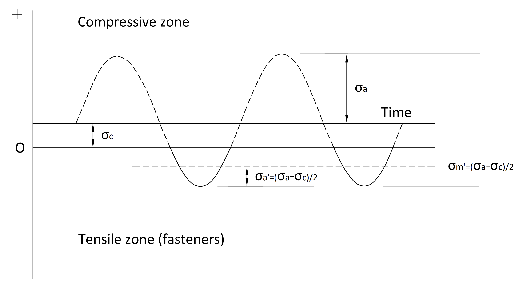
It can be deduced that, for the described load state, the tensile stresses supported by the bolts of the joint are:
\sigma'_a = \sigma'_m = \Large \frac{\sigma_a - \sigma_c}{2}\normalsize, for \sigma_a > \sigma_c
Where:
- \sigma_a : alternating stress produced by moment.
- \sigma_c : compressive stress produced by the constant axial load.
Although, in this project all possible combinations between the alternating load produced by the moment and the compressive load produced by the axial load have been studied, it is the described combination the one that has more value for Tecma Drive S.L. and, therefore, the one we show in this blog.
Fatigue criteria
The recognized fatigue criteria are as follows:
- Soderberg
- Modified Goodman
- Gerber
- ASME-elliptic
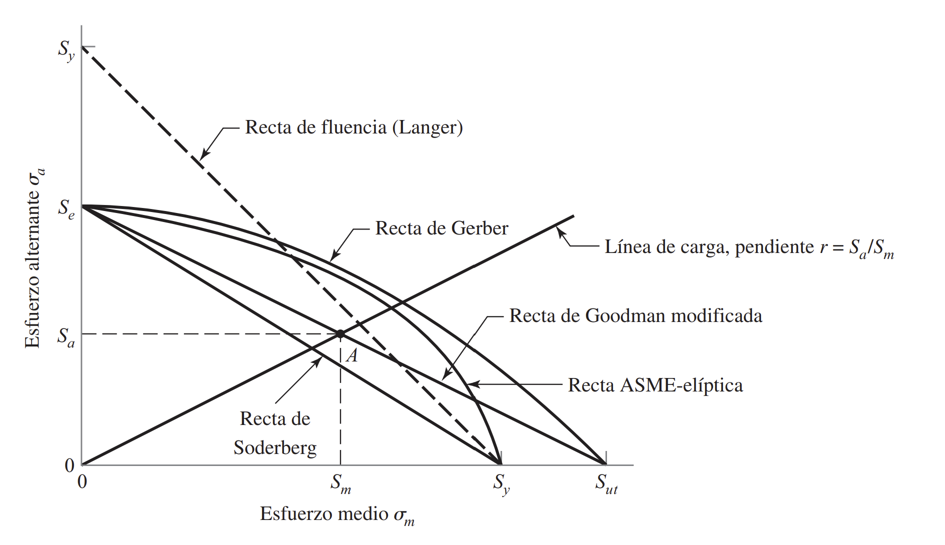
The equations for these criteria are described in our handbook Fatigue in the section on fluctuating stresses.
For this project, the Soderberg approach has been taken as it is the most restrictive of all, in order to be on the safe side:
\Large \frac{\sigma'_a}{S_e} \normalsize + \Large \frac{\sigma'_m}{S_y} \normalsize = 1
Knowing that:
\sigma'_a = \sigma'_m = \Large \frac{\sigma_a - \sigma_c}{2}
\sigma_a \Large \frac{4 M}{n \phi A_s}
\sigma_c \Large \frac{R_a}{n A_s}
By substituting the stresses by the loads that provide them in the equation of the Soderberg approach we have that:
\sigma_a = \Large \frac{2 S_e S_y}{S_e + S_y} \normalsize + \sigma_c
\Large \frac{4M}{n \phi A_s} = \Large \frac{2 S_e S_y}{S_e + S_y} \normalsize + \Large \frac{R_a}{n A_s}
By reordering terms, we have the line that limits the fasteners to fatigue:
M = M* + \Large \frac{\phi}{4} \normalsize R_a
Where:
M* = M_{Sod} = \Large \frac{n \phi A_s S_e S_y}{2(S_e + S_y)}
And it indicates the alternating moment that produces fatigue failure by the Soderberg approach at infinite life ( 10^6 > ciclos) on the fastener with zero axial load.
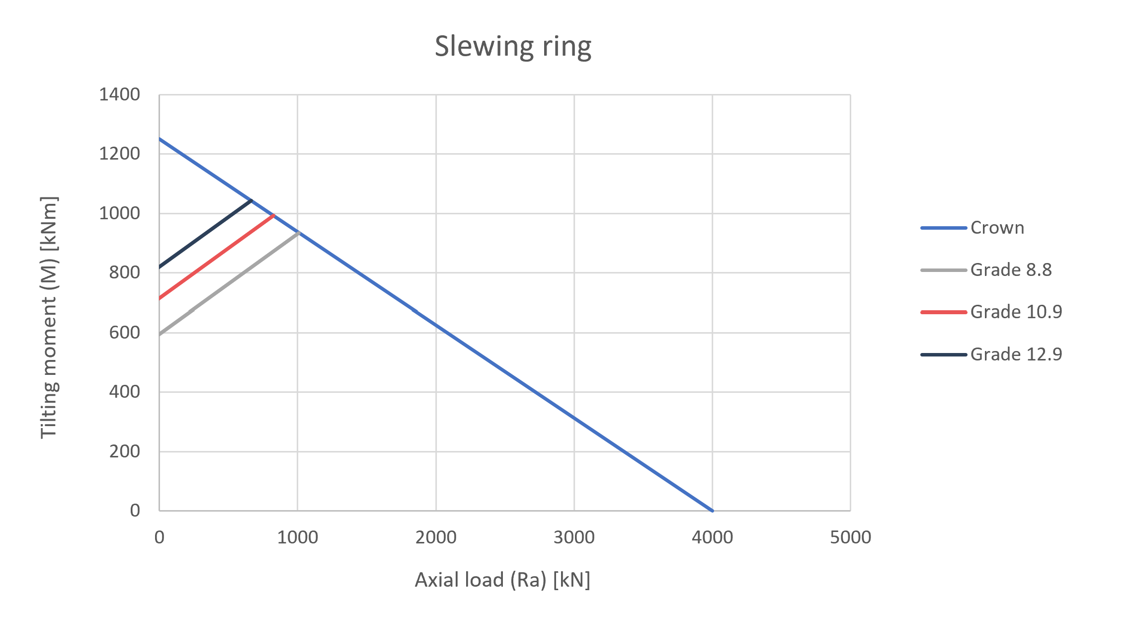
This limit line can be adapted to the different fatigue criteria by replacing the alternating moments with zero axial load ( M* ) for each of them:
M_{ASME-Elíptica} = \Large \frac{n \phi A_s S_e S_y}{2 \sqrt{(S_e + S_y)}}
M_{Goodman} = \Large \frac{n \phi A_s S_e S_{ut}}{2(S_e + S_{ut})}
M_{Gerber} = \Large \frac{1}{4} \normalsize n \phi A_s S^2_{ut} \left(- \Large \frac{1}{S_e} \normalsize + \Large \sqrt( \frac{1}{S^2_e} \normalsize + \Large \frac{4}{S^2_{ut}}) \right)
With:
- n : number of screws in the crown
- \phi : diameter where the screws are placed in the inner crown
- A_s : resistant section
- S_e : fatigue limit
- S_{ut} : ultimate stress
- S_y : yield limit
According to Eurocode 3, prestressed fasteners have two main verifications:
- Sliding design
- Tensile design
For prestressed connections, the standard classifies the sliding design as category C and category E for the tensile design.
Sliding design
Design sliding resistance according to Eurocode 3 ( F_{s,RD} ) should be taken as follows:
F_{s,Rd} = \Large \frac{k_s n \mu (F_{p,C} - 0.8 F_{t,Ed})}{\gamma_{M3}}
Where:
- k_s : is a parameter that depends on the bolt hole and is equal to 1 for standardized holes. See table in the annexes.
- n : number of sliding planes. Normally 1 for slewing rings.
- \mu : is the friction coefficient obtained either by specific tests for the friction surface or according to table 3.7 when applicable.
- F_{p,C} : prestressing force.
F_{p,C} = 0.7 S_{ut} A_s
With:
-
-
- S_{ut} : bolt ultimate stress.
- A_s : bolt resistant area.
-
- F_{t,Ed} : Axial tensile force, which particularized for the most stressed bolt in the bearing joint, is as follows:
F_{t,Ed} = \Large \frac{4M}{n \phi} \normalsize + \Large \frac{R_a}{n}
For more information, please see our handbook Bolted Circular Flanges
- \gamma_{M3} : partial safety coefficient, which is 1.25 according to the standard.
Known the sliding resistance ( F_{s,Rd} ), the most requested bolt, and therefore the joint, will comply to sliding design versus shear stress ( F_{v,Ed} ) if:
\Large \frac {F_{s,Rd}} {F_{v,Ed}} \normalsize = \Large \frac {n F_{s,Rd}} {R_v} \normalsize > 1
Where R_v is the shear stress on the slewing ring.
Tensile design
Design tensile resistance in accordance with Eurocode 3 ( F_{t,Rd} ) should be taken as follows:
F_{t,Rd} = \Large \frac {k_2 S_{ut} A_s} {\gamma_{M2}}
Where:
- k_2 : is a parameter that depends on the bolt shape which is 0.9 for cases where the bolt is not countersunk.
- S_{ut} : bolt ultimate stress.
- A_s : bolt resistant area.
- \gamma_{M2} : partial safety coefficient that the standard marks as 1.25.
Knowing the tensile strength ( F_{t,Rd} ), the most requested bolt, and therefore the joint, will meet the tensile axial force ( F_{t,Ed} ) if:
\Large \frac{F_{t,Rd}}{F_{t,Ed}} \normalsize = \Large \frac{n F_{t,Rd}}{R_a} \normalsize >1
With R_a as the axial tensile stress on the slewing ring.
Resultados
Se ha estudiado la tornillería de calidades 8.8, 10.9 y 12.9 frente a cargas estáticas y fatiga en el campo de los rodamientos de grandes dimensiones. Se ha desarrollado una herramienta en hoja Excel en la que se recogen los procedimientos para enmarcar los cálculos de fatiga de la tornillería en las gráficas M-Ra del catálogo de Tecma Drive S.L.
Se exponen, a continuación, las gráficas de comportamiento de los tornillos cuando la carga axial es de tracción además de compresión.
