Hydraulic Threads
There are certain threads that were designed to achieve the sealing in hydraulic circuits:
System BSP (British Standard Pipe)
This British standard is the most widespread in Europe, it has 55º between threads. It can be parallel (BSPP) or tapered (BSPT).
BSPP (Parallel) ISO 228-1
Also called Gas (G) type threads, it is a cylindrical thread that does not achieve sealing with thread flanks but with the contact of two surfaces by means of a gasket. For its external thread, there are two tolerances: A (tighter class) and B (wider class). The former is the most commonly used. Its internal thread is used in block machining because of its simplicity.
Designation:
Tight external thread: G 1-1/2 A ISO 228-1
Wide external thread:: G 1-1/2 B ISO 228-1
Internal thread: G 1-1/2 ISO 228-1
Wide external thread:: G 1-1/2 B ISO 228-1
Internal thread: G 1-1/2 ISO 228-1
BSPT (Tapered) ISO 7-1
A tapered thread with a taper angle of 1.47º. It achieves the sealing by tightening between the flanks of its teeth. Its internal thread can be tapered, designated by Rc, or cylindrical designated by Rp.
Designation:
External thread: R 1-1/4 ISO 7-1
Cylindrical internal thread: Rp 1-1/4 ISO 7-1
Tapered internal thread: Rc 1-1/4 ISO 7-1
Cylindrical internal thread: Rp 1-1/4 ISO 7-1
Tapered internal thread: Rc 1-1/4 ISO 7-1
Although the BSPT external thread can screw into the BSPP internal thread, the use of a sealant is advised and is not recommended for pressurized fluid applications.
System NTP (National Thread Pipe)
It is the American standard for hydraulic applications and the most widespread in the USA and Canada. It has an angle of 60º between thread threads and a taper of 1.47º.
Designation:
[thread diameter]-[pitch] NPT ASME B1.20.1
3/8-18 NPT ASME B1.20.1
The British (BSP) and American (NPT) systems are not compatible. However, there are hydraulic fittings which, in addition to changing thread sizes in the same system, can also change from one system to the other even between BSPP and BSPT.
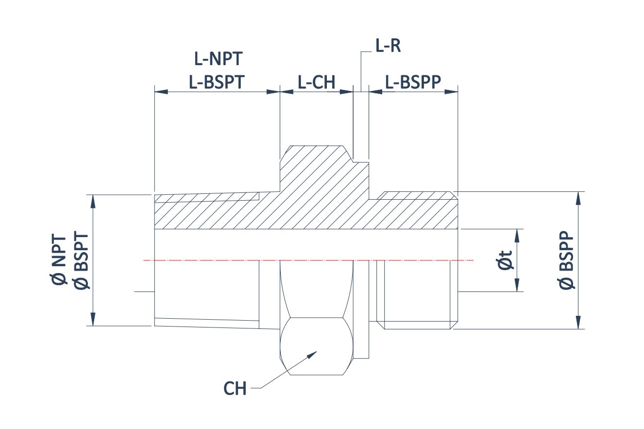
A table of these fittings is shown for the most common sizes:

Hydraulic fitting
| BSP (") | φ-BSP | φt | CH | L-BSPT | L-BSPP | L-HEX | L-R | NPT (") | φ-NTP | L-NPT |
|---|---|---|---|---|---|---|---|---|---|---|
| 1/8 | 9.73 | 4.5 | 14 | 10 | 8 | 5 | 1 | 1/8-27 | 10.24 | 10 |
| 1/4 | 13.16 | 6 | 19 | 12 | 10 | 7 | 1 | 1/4-18 | 13.61 | 14.5 |
| 3/8 | 16.66 | 9 | 22 | 12 | 12 | 7 | 2 | 3/8-18 | 17.06 | 15 |
| 1/2 | 20.96 | 13 | 27 | 19 | 14 | 7 | 3 | 1/2-14 | 21.23 | 19 |
| 3/4 | 26.44 | 17.5 | 32 | 20 | 16 | 8 | 3 | 3/4-14 | 26.57 | 20 |
| 1 | 33.25 | 23 | 41 | 18 | 18 | 10 | 3 | 1-11.5 | 33.23 | 24 |
| 1 1/4 | 41.91 | 30 | 50 | 20 | 20 | 11 | 3,5 | 1 1/4-11.5 | 41.99 | 25 |
| 1 1/2 | 47.80 | 37 | 55 | 22 | 22 | 12 | 2,5 | 1 1/2-11.5 | 48.05 | 26 |
| 2 | 59.61 | 45 | 70 | 26 | 22 | 13 | 2 | 2-11.5 | 60.09 | 26 |
All values in the table are in millimeters except those marked in inches with (").
For hydraulic applications it is possible to use metric DIN threads and unified inch (UN) threads for specific applications. But at no time will they achieve sealing between the threads, so O-rings and metalloplastic washers must be used as in the parallel BSP system (BSPP).


