Welds

Welds

Welded joints can be classified according to the relative position of the welded plates:
Fillet welds
In this type of configuration no edge preparation is performed on the edges of the parts to be joined before welding and the penetration of the bead is exclusively due to the fusion generated during the process.
Butt welds
Before welding, an edge preparation is made on the parts, in order to favor the bead penetration (it is not necessary in thin parts).
At the same time, in the butt joints can be distinguished:
a) Complete penetration: when the fusion and mixing between the base material and the filler material reaches the entire thickness of the joint.
b) Partial penetration: if this fusion and mixing does not reach the entire thickness.

Resistencia

The resistance calculation of a weld seam has an experimental basis and is based on the experience obtained. That is why there is no single, universal criterion; each standard or country has its own criterion. However, any of the existing calculation standards can be taken as a reference, as they implicitly or explicitly assume the following common bases on which their respective calculation criteria are based:
1) Rules of good practice have been followed during the execution of the weld whose resistance is intended to be calculated at all time.
2) Mechanical-resistant characteristics of the filler metal are at least equal to those of the base metal.
3) The design of the seam has avoided the danger of a fragile breakage by means of the opportune choice of the material and the suitable constructive details.
According to the second hypothesis, butt joints with full penetration do not need to be calculated, and it is evident that their loading capacity will be higher or at least equal to those of the parts they join (however, it is necessary to check joints subjected to dynamic loads).
Therefore, in what follows, the mechanical calculation of welded joints will be focused on the case of fillet joints, and all the theoretical development that will be presented below will be applicable to this type of joints.
To begin with the study of fillet welds, we will define what is called the throat plane of the weld bead. In these fillet seams, the so-called throat plane is defined as the one determined by the intersection line of the two planes to be joined and the height of the largest isosceles triangle that can be inscribed in the section of the seam. This height is called the throat or throat thickness, or simply bead throat (a).
Triedro soldadura
Throat section stress
Therefore, the weld bead can be assimilated to an isosceles triangle of which the section defined by the height "a" (throat of the bead) of said isosceles triangle will be taken as the calculation section, since it has the smallest section.
Likewise, it will be considered that the stresses are constant along the plane defined by the height "a" and whose surface is “a·L”, where L is the length of the weld bead.

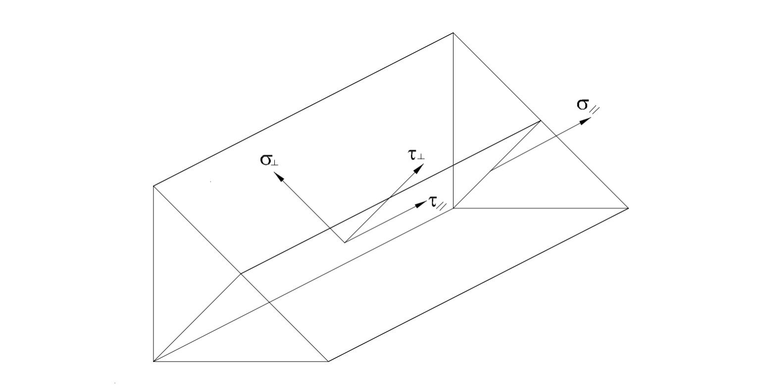
Then, on this plane, the stress components generated in a weld bead will be defined: one stress normal to the plane \sigma_{\bot} , and two other components on the reference plane and perpendicular to each other \tau_{\bot} and \tau_{//} .

From these stresses, each standard sets up its own calculation expression, obtained from an experimental basis, which gives the ultimate resistance of a weld bead.
According to CTE:

\sqrt {\sigma_{\bot}^2 + 3 (\tau_{\bot}^2+ \tau_{//}^2)} < \Large \frac{f_u}{\beta_w   \gamma_{M2}}

\sigma_{\bot} < \Large \frac{f_u}{\gamma_{M2}}

Siendo:

f_u : ultimate tensile strength of the weakest member of the joint.

\gamma_{M2} : safety coefficient, value 1.25.

\beta_{w} : correlation coefficient, as given in the following table:

Steelfu (Mpa)βw
S2353600.80
S2754300.85
S3555100.90
Sometimes, the stresses described in the weld throat plane are more manageable if they are projected on the faces of the weld.
Triedro abatido
Welding face stresses
On this projected face, stresses (n, tn, ta) are defined as shown in the figure above.
Now, it only remains to relate both sets of stresses:

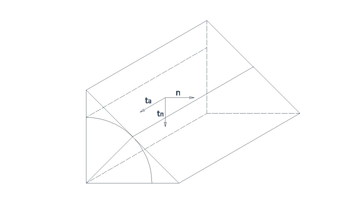
\sigma_{\bot} = \Large \frac{1}{\sqrt{2}} \normalsize \cdot (n+t_n)

\tau_{\bot} = \Large \frac{1}{\sqrt{2}} \normalsize \cdot (n-t_n)

\tau_{//} = t_a

So, the comparison stress will be:

\sqrt {2 (n^2+t_n^2-n\cdot tn) +3t_a^2} < \Large \frac{f_u}{\beta_w   \gamma_{M2}}

\Large \frac{1}{\sqrt{2}} \normalsize \cdot (n+t_n) < \Large \frac{f_u}{  \gamma_{M2}}

Symbology

The symbolic representation for welded joints drawings is marked in the standard ISO 2553.
Simbologia 2-EN
Symbology
1) Arrow line.
2) Intersection (optional). A circle may appear indicating a closed circumferential weld or a flag marking a weld during assembly operations.
3) Weld dimension. For fillet welds, it is indicated with an "a" followed by the dimension in millimeters to indicate the throat size. Alternatively, the "a" can be replaced by a "z" to indicate the size of the weld face. Optionally, an "s" can be added in front with a dimension to indicate the penetration if it is necessary to mark it. The penetration size includes the throat size. Butt welds are simply marked with the above-mentioned "s" followed by their size.
4) Supplementary symbol (optional). If a certain finishing is desired on the visible surface of the weld.
5) Weld symbol. It is usually related to the weld section. The standard marks the symbol for each type.
6) Number and length of traces (optional). If the weld is not continuous, the number of traces can be marked in the place of letter "n" and its length in the place of letter "l" in millimeters.
7) Staggered (optional). It indicates whether a double-sided dashed weld is to be staggered.
8) Space among traces (optional). Space separating the weld traces if the weld is not continuous. It is replaced by the letter "e", always in parentheses.
9) Tail. The following aspects must be marked in the tail of the weld symbol to fully defined a welded joint:
Quality (ISO 5817)
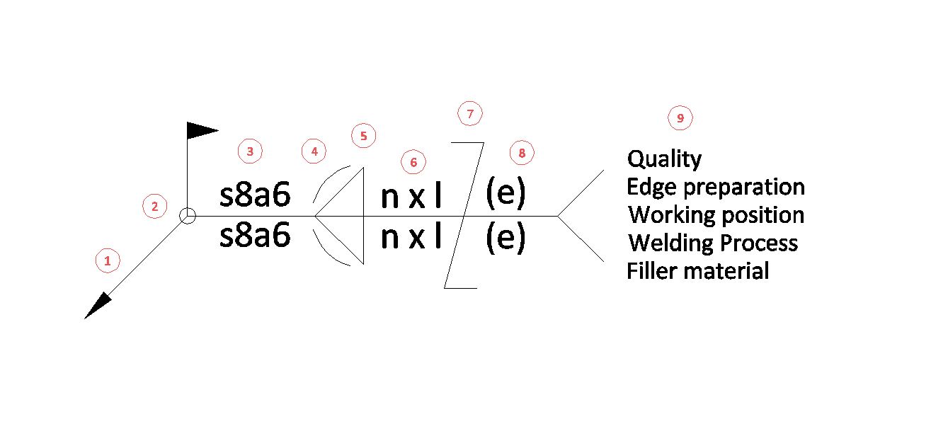
Edge preparation (ISO 9692)
Working position (ISO 6947)
Welding process (ISO 4063)
Filler material
The first two are defined by Design, the others by Execution.

Quality

The different aspects of weld quality are defined by the ISO 5817 standard. This standard lists all possible imperfections in the weld and narrows them into ranges depending on 3 categories:
B/ EN ISO 5817. It is the most demanding of the 3 ones and should be noted for any weld that is structural and resistive.
C/ EN ISO 5817. The intermediate category. It is used for welds that are not resistive.
D/ EN ISO 5817. It is the least demanding and is not usually used for technical welds.

Edge preparation

The standard ISO 9692 defines the recommendations and codifies the preparations of parts to be joined depending on the type of joint and welding process to be used. It has four parts.
ISO 9692-1. Welding and allied processes. Preparations.
Part 1. Manual metal arc welding, gas-shielded metal arc welding, gas welding, TIG welding and beam welding of steels.
ISO 9692-2. Welding and allied processes. Preparations.
Part 2. Submerged arc welding of steels
ISO 9692-3. Welding and allied processes. Preparations.
Part 3: Metal inert gas welding and tungsten inert gas welding of aluminum and its alloys.
ISO 9692-4. Welding and allied processes. Recommendations for joint preparations.
Parte 4: Aceros Part 4: Clad steels.
Below is a table with the most common edge coding for the welding processes described in the more general ISO 9692-1:
CódigoTipo de preparación
1.2.1 / EN ISO 9692-1SPB (a tope), t ≤ 4mm
1.2.2 / EN ISO 9692-1SPB (a tope), 3 < t ≤ 8mm
1.3 / EN ISO 9692-1En V simple, 3 < t ≤ 10
1.4 / EN ISO 9692-1
En V simple con bisel cerrado, t > 16
1.5 / EN ISO 9692-1
En V simple con talón amplio (Y), 5 ≤ t ≤ 40
1.9.1 / EN ISO 9692-1
Con bisel simple (chapas en ángulo), 3 < t ≤ 10
1.9.2 / EN ISO 9692-1
Con bisel simple (chapas a tope), 3 < t ≤ 10
2.1 / EN ISO 9692-1
SPB (a tope), t ≤ 8
2.2 / EN ISO 9692-1
En V simple 3 ≤ t ≤ 40
2.5.1 / EN ISO 9692-1
En V doble (X), t > 10
2.8 / EN ISO 9692-1
Con bisel simple 3 ≤ t ≤ 30
2.9.1 / EN ISO 9692-1
Con bisel doble (K), t > 10 (chapas a tope)
2.9.2 / EN ISO 9692-1
Con bisel doble (K), t > 10 (chapas a tope)
3.1.1 / EN ISO 9692-1
SPB. Triángulo t > 2 (chapas chapas a 180º)
3.1.2 / EN ISO 9692-1
SPB. Triángulo t > 2 (chapas chapas a 180º)
3.1.3 / EN ISO 9692-1
SPB. Doble Triángulo t > 3 (chapas chapas a 270º)
4.1.1 / EN ISO 9692-1
SPB. Doble Triángulo t > 3 (chapas chapas a 270º)
4.1.3 / EN ISO 9692-1
SPB. Doble Triángulo t > 3 (chapas chapas 90º)
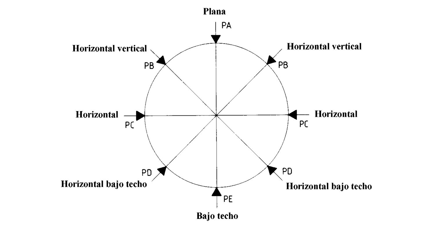
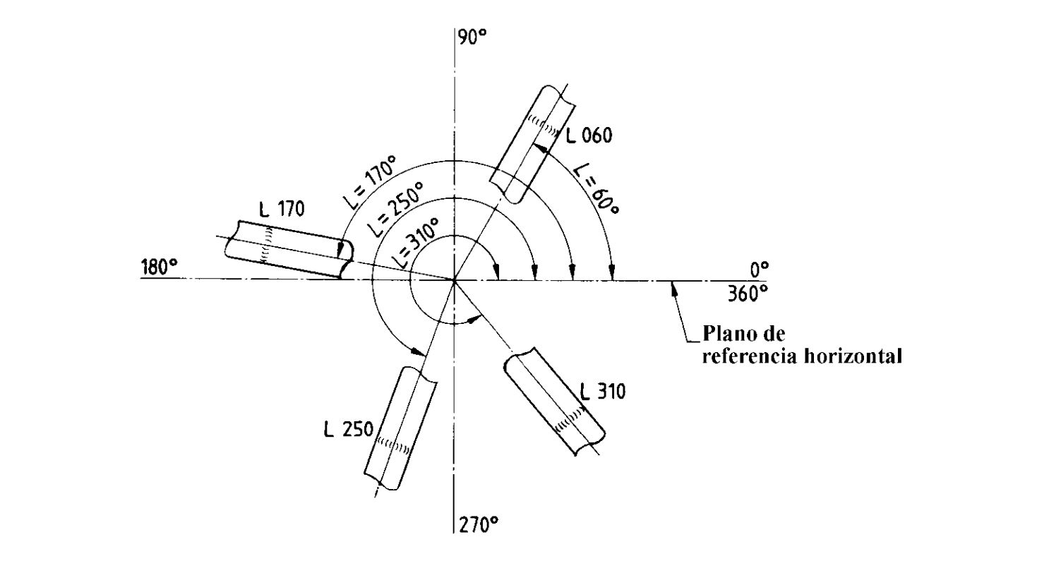
SPB = Without edge praparation.

Working positions

Working positions for welding process are defined by the standard ISO 6947.
The main positions are defined in the following table:
PosiciónSímboloPendiente (S)Rotación (R)
PlanaPA/ EN ISO 694790º
Horizontal verticalPB/ EN ISO 694745º
135º
Horizontal horizontalPC/ EN ISO 6947
180º
Horizontal bajo techoPD/ EN ISO 6947225º
315º
Bajo techoPE/ EN ISO 6947270º
Vertical ascendentePF/ EN ISO 694790º--
Vertical descendentePG/ EN ISO 6947270º--
Posiciones de trabajo
Main working positions
Slope (S) is the inclination of the weld bead with respect to the horizontal plane.
Rotation (R) is the angle of the welder with respect to the weld origin position. If we take the weld at the origin as reference:
0º: welder from the right towards the origin.
90º: welder from the top towards the origin.
180º: welder from the left towards the origin.
270º: weld from the bottom towards the origin.
For no main positions, it is designated by the slope angle (S) and the rotation angle (R), separated by a dash.
Example:
030-090 (30° slope with a 90° rotation).

Pipes

For circumferential welds on pipes, working positions are designated by the letter "L" and the inclination of the pipe axis with respect to the horizontal (preferably between 0º and 180º), preceded by the following letters, separated by a dash:
H: upward weld
J: downward weld
K: orbital weld
Example:
H-L030 (pipe oriented 30º with respect to horizontal plane, upward weld)
Circunferenciales
Pipe welds

Welding Processes

The standard ISO 4063 assigns a code to each welding process to identify them without margin of error.
The most common ones are listed below:
CódigoProceso de soldadura
3/ EN ISO 4063Soldeo por llama
111/ EN ISO 4063Soldeo por arco con electrodo revestido
121/ EN ISO 4063Soldeo por arco sumergido (SAW) con electrodo de hilo (alambre) de aceros
131/ EN ISO 4063Soldeo por arco con gas inerte; soldeo MIG
135/ EN ISO 4063Soldeo por arco con gas activo; soldeo MAG
141/ EN ISO 4063Soldeo por arco con gas inerte y electrodo de volframio; soldeo TIG
21/ EN ISO 4063Soldeo por puntos
52/ EN ISO 4063Soldeo laser

Filler Materials

They depend on the materials to be joined and the welding process.
Attached is a table with some common consumables and their welding process:
Materiales a unirMaterial de aporteProceso de soldadura
Aceros de construcciónAWS A5.18: ER70S-6135
Aceros de alta resistenciaAWS A5.1 E7018-1111
INOX 316DIN 8556:316LSI135
INOX 309 e INOX disimilaresCODEMIG 309L / AWS A5.9: ER309L135
Chapa galvanizada CODEMIG CuSi3 / AWS A5.7: ER CuSi-A131
Aceros a presiónAWS/ASME SFA 5.17:EM 12K 121
INOX, cobre y níquel
EWTh-2/EN ISO 6848141
Aluminio y Magnesio
EWP/EN ISO 6848
141