Carports. Free vs blocked wind flow
En nuestro post FEM Marquesinas. Elementos beam vs solid, definimos la combinación de carga más desfavorable para el pórtico de una marquesina a un agua para el aparcamiento de automóviles. Concretamente:
1.35PP+1.35PM+0.9VP+1.5N
Being:
- PP: Self-weight
- PM: Dead loads
- VP: pressure wind
- N: Snow
This combination is the most unfavorable for the structure because it produces the maximum moment at the pilar base due to the fact that the forces of wind pressure and snow contribute to maximize this stress.
It should be remembered that the Technical Building Code (CTE) considers that wind forces on carports always have two opposite directions of application on the surface where they are applied.
Snow loads, however, only have a single direction of application, which coincides with gravity, since the snow loads considered by the standard, for practical purposes, is a dead weight on the structure that is affected by gravity.
When the predominant direction of wind loads approaches the predominant direction of wind loads in canopies with this geometry, the maximum moments occur at the pilar base of portal frames.
This happens when carports allow free wind flow under their roof.
However, the CTE regulations also analyze cases where the carports is completely blocked under its roof for any reason.
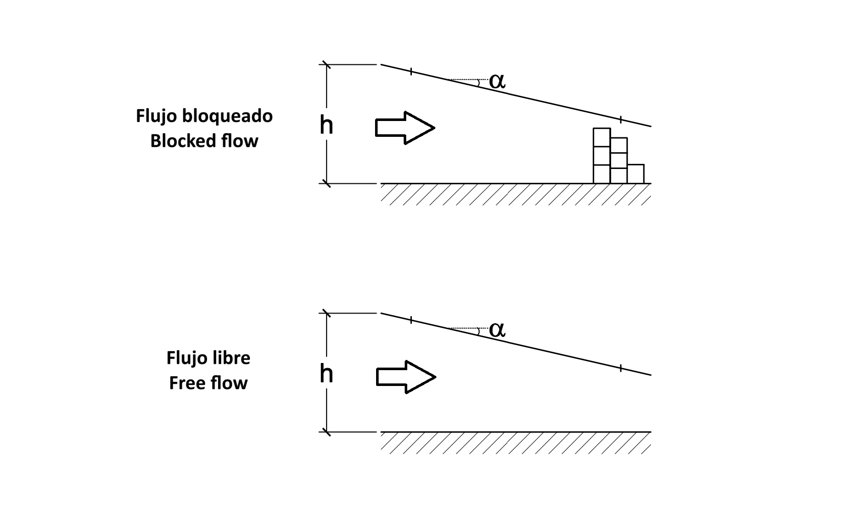
In the case of carports, it is very common to have a wall that delimits the parcels of land next to which the carports are installed.
In these situations, the CTE increases the suction coefficient for carports whose inclination is around 5 degrees from -0.7 to -1.4. This doubles the suction wind load to be considered in the load combinations, maintaining the same coefficients for the pressure wind loads.
In the following images, we show the structure calculated in our post FEM Carports. Beam vs solid elements, with a blocked wind flow.
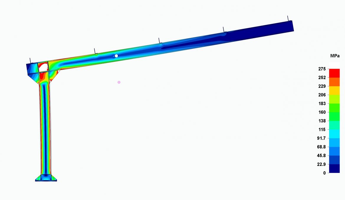
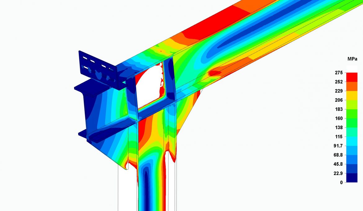
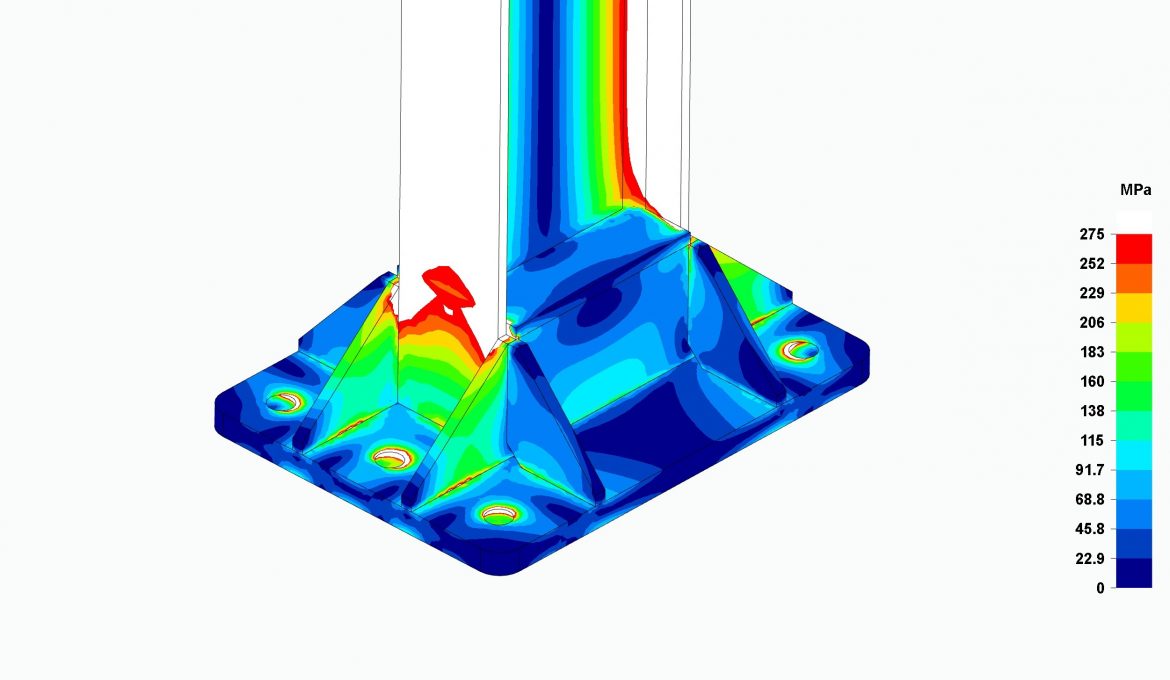
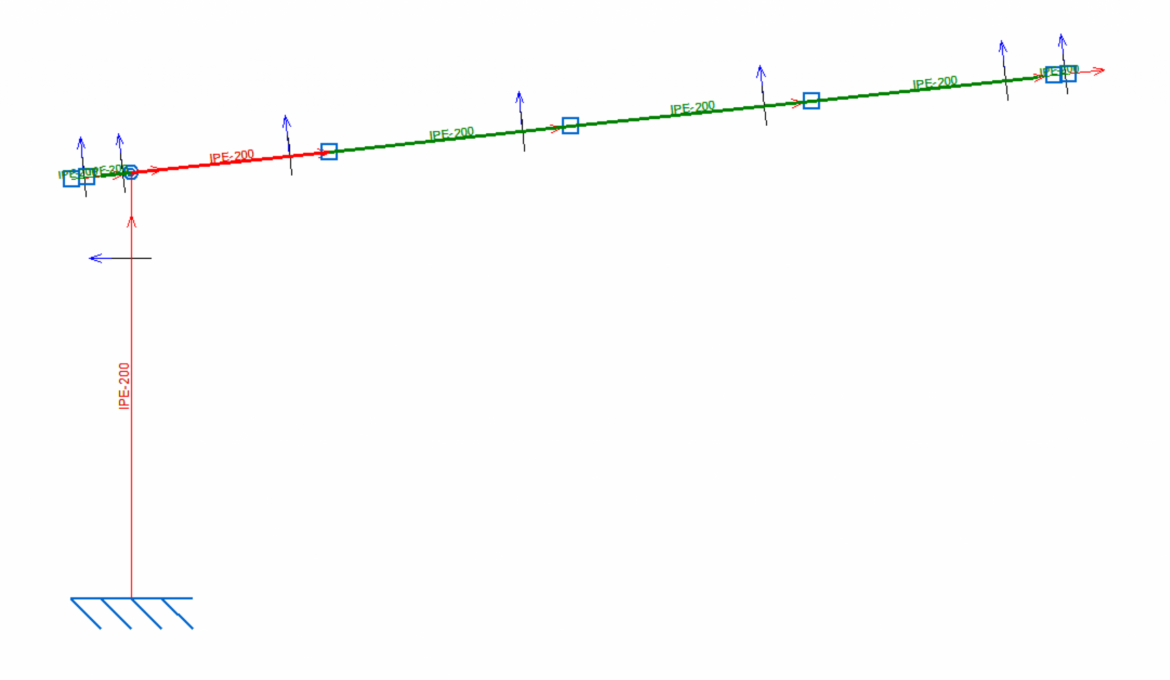
It can be seen that, by doubling the suction wind load, this portal frame would not comply with the CTE. The stresses in the white zones for programs using solid elements and the red zones for programs using beam elements exceed the elastic limit of the material forming the portal frame.
Since the direction of the snow load is always downward and a suction load is generally, and in this case, upward, it would be possible for such a suction wind load to generate a maximum moment at the pilar base greater than that produced by the snow loads together with the pressure wind loads.
Translated to load combinations according to CTE:
0.8PP+0.8PM-1.5VS_b > 1.35PP+1.35PM+0.9VP+1.5N
Being VS_b the suction wind load in blocked flow.
In the scope of the CTE standards, the moment produced by the suction wind forces causes higher moments at the pilar base of carports than the pressure wind forces together with the snow loads, if the carports does not allow the free flow of wind under its roof and as long as the snow load is low.
Our reference location for the carport calculation has been Seville, which has the lowest snow load in Spain. If this load starts to rise for other territories, again the pressure wind load plus the snow load will produce higher moments than the suction wind load. But where is this limit?
To calculate it qualitatively we will make the following assumptions:
Assuming these premises we can state the following equation:
0.8PP+0.8PM-1.5VS_b = 1.35PP+1.35PM+0.9VP+1.5N
By isolating the snow load (N), we have:
N = - \Large \frac{0.55PP+0.55PM+0.9VP+1.5VS_b}{1.5}
Together with the described loads:
| Loads | Value [N] |
|---|---|
| Own weight (PP) | 230 (*) |
| Dead loads (PM) | 450 |
| Pressure wind (VP) | 1130 |
| Suction wind (VSb) | -3960 |
| Snow (N) | To be calculated |
(*) Portal frame self-weight that influences the pilar base moment.
Substituting these values in our expression, we have:
N = 3033 N
When the purlin support load is 3033N, the pressure wind loads plus the snow loads produce the same moment at the pilar base as the suction wind forces. When the snow loads are greater than this value the former produce the most unfavorable load combination on the structure.
In our post FEM Carports. Elementos beam vs solid, we calculated that a snow pressure of 200N/m² dictated by the CTE for the Seville location is equivalent to 1000N of load on each of the 5 supports of each purlin on the portal frame beam, so those 3033N are equivalent to 607N/m² pressure. We will call this parameter Snow limit ( S_l ).
This tells us that for locations or cities where the snow pressure is around 0.607kN/m2 for a carport-blocked configuration, the moment produced at the pilar base by the pressure wind loads plus the snow loads are approximately equal to those produced by the suction wind loads. If the snow pressure is greater than this value, the snow load plus the pressure load will be more unfavorable in the carport design; if, on the contrary, it is less, the suction snow loads will be, in this case, more critical.
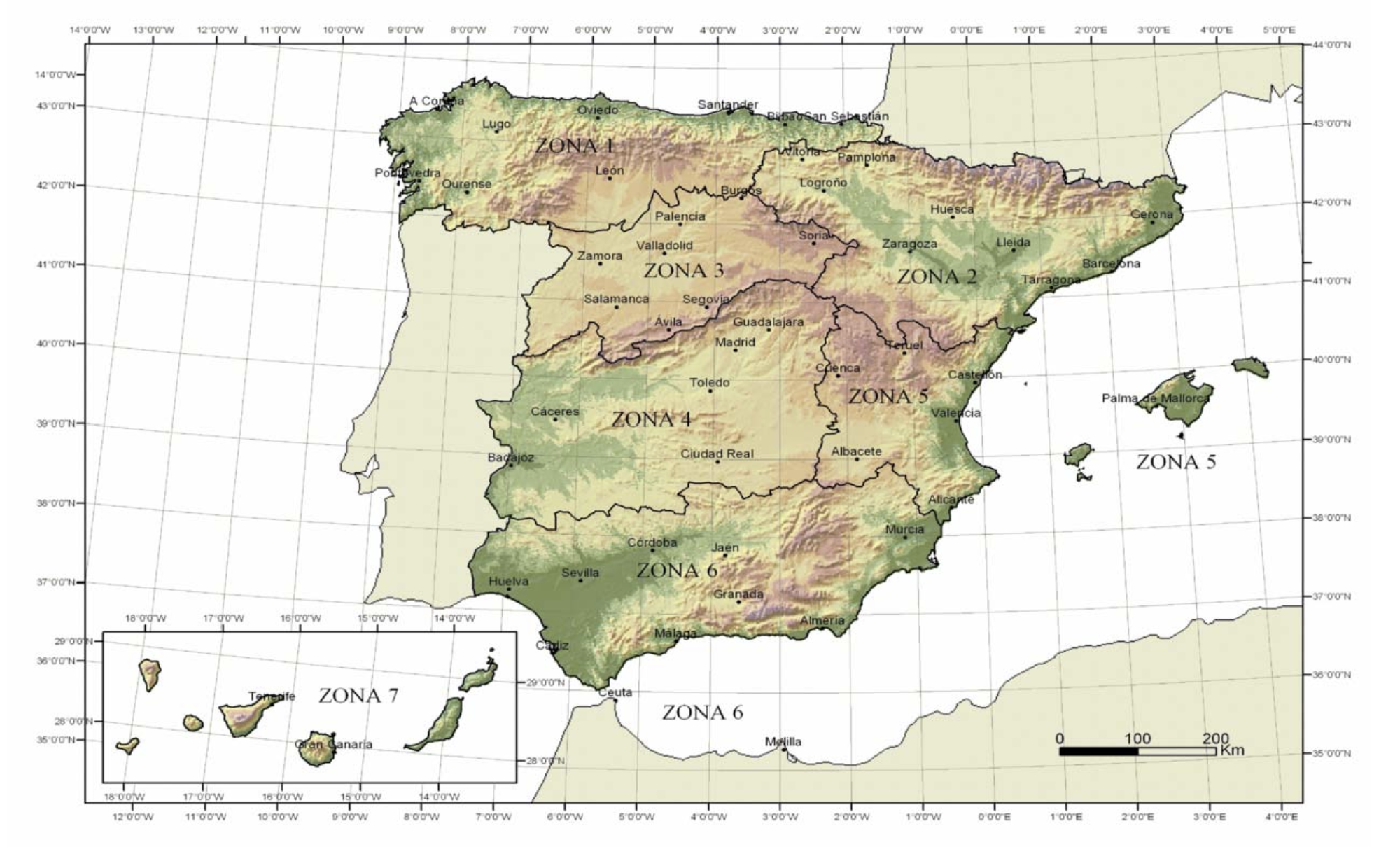
According to the CTE in Spain there are 7 snow zones, but there are data on the pressure to be applied by provincial capitals since the snow load depends a lot on the height of the structures above sea level, so, for example, the lowest snow pressure is 0.2kN/m2 for the cities of Seville, Cadiz or Valencia and the highest for León is 1.2kN/m2.
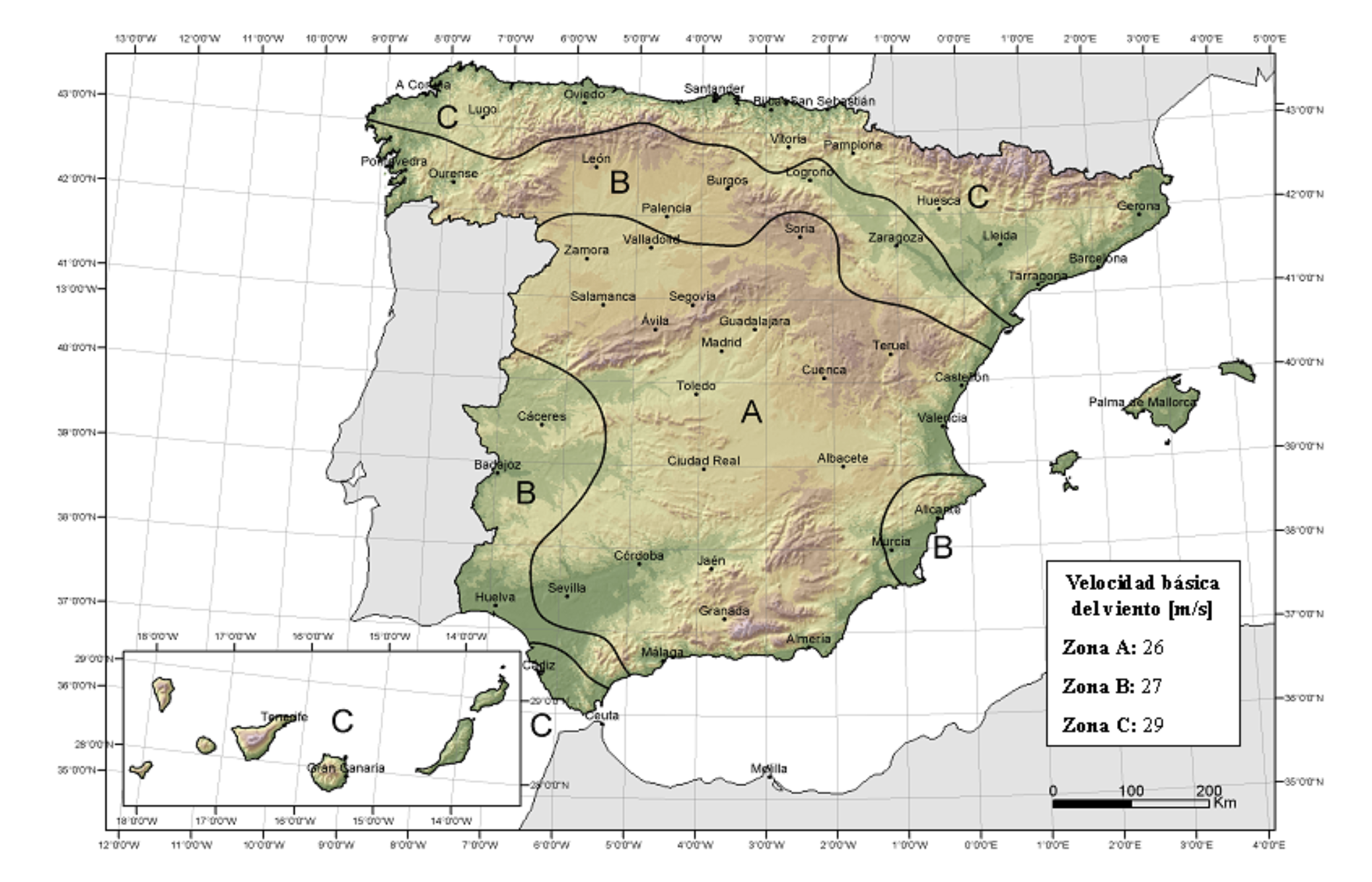
In the CTE, 3 different wind speed zones are also marked, with values of 26m/s in zone A, 27m/s in zone B and 29m/s in zone C. The wind load increases with the square of the wind speed, so that the wind load in zone B is, a priori, 7.8% higher than in zone A, and 24.4% in zone C with respect to zone A. On the other hand, the wind load in zone C is 15.4% higher than in zone B.
Moving from zone A (Seville) to zone C would increase the wind loads considerably, by 24.4%, but it would increase for both pressure wind loads and suction wind loads, so the suction wind loads would never be so important as to compensate for the pressure wind loads together with the snow loads. The portal frame structure would have to be recalculated if moved to zone B or C because the wind loads quantitatively go up in value, but not because of a mismatch between pressure vs. suction wind loads as happens in blocked carports.
The Snow limit ( S_l ) changes for the 3 CTE wind zones because the wind loads are different for each of them.
For each of the 3 wind zones we have the following loads:
| Value [N] | |||
|---|---|---|---|
| Loads | Zona A | Zona B | Zona C |
| Own weight (PP) | 230 (*) | ||
| Dead loads (PM) | 450 | ||
| Pressure wind (VP) | 1130 | 1218 | 1405 |
| Suction wind (VSb) | -3960 | -4270 | -4926 |
| Snow (N) | To be calculated | ||
The snow load that, in these cases, equals the moments produced by the pressure wind load plus the snow with those produced by the suction winds is the following as seen in previous paragraphs:
N = - \Large \frac{0.55PP+0.55PM+0.9VP+1.5VS_b}{1.5}
| Zona A | Zona B | Zona C | |
|---|---|---|---|
| Carga de nieve [N] | 3033 | 3290 | 3822 |
| Límite de nieve (Sl) [kN/m2] | 0.607 | 0.658 | 0.766 |
Since the suction wind load is higher than the pressure wind load, by increasing them by the factor of the square of the velocity, the snow loads will have to increase to compensate for a higher moment produced by the suction wind load.
After studying the wind and snow loads, the influence of these loads on the moment at the base of the column, which defines the dimensions of the elements that make up the carports, and how blocking the flow increases the values of this moment, it is possible to determine the relationships between the wind and snow loads established by the CTE to define the reference IPE profiles with which to build the carport portal frames for any city in Spain.
Thus, we have the IPE profiles for carports that allow the flow under their roof:
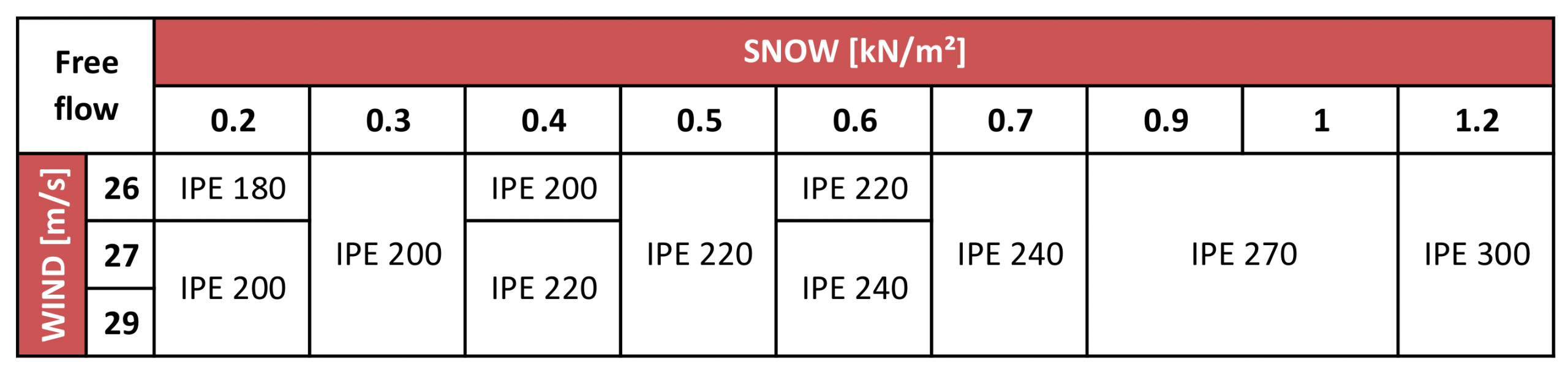
The same table is shown below for blocked flows:
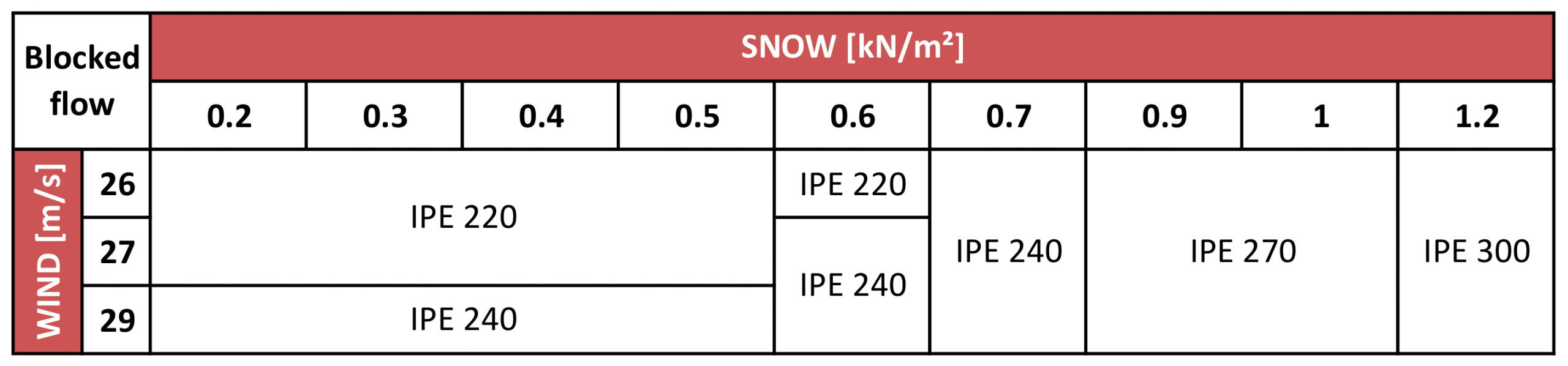
If we compare both tables, at low snow loads where the snow limit is not exceeded (left part of the tables), the IPE profiles forming the structure are larger at blocked flows mainly because the suction wind load produces higher column base moments. We also see that an increase in snow load does not provide an increase in the size of the profiles composing the structure. Once this Snow limit ( S_l ) is passed, around 0.6kN/m2, the suction wind loads no longer play a role in the worst-case load combination, so the wind pressure loads plus the snow load define the design of the portal frame profiles and these loads are equal for both the free and blocked flow cases (right side of the tables).
It should be noted that the values in the tables are approximate; the final configuration of the profiles that make up a carport must be designed exclusively for the specific project in question.
The following table provides information on the cities in Spain that would have the same carport configuration
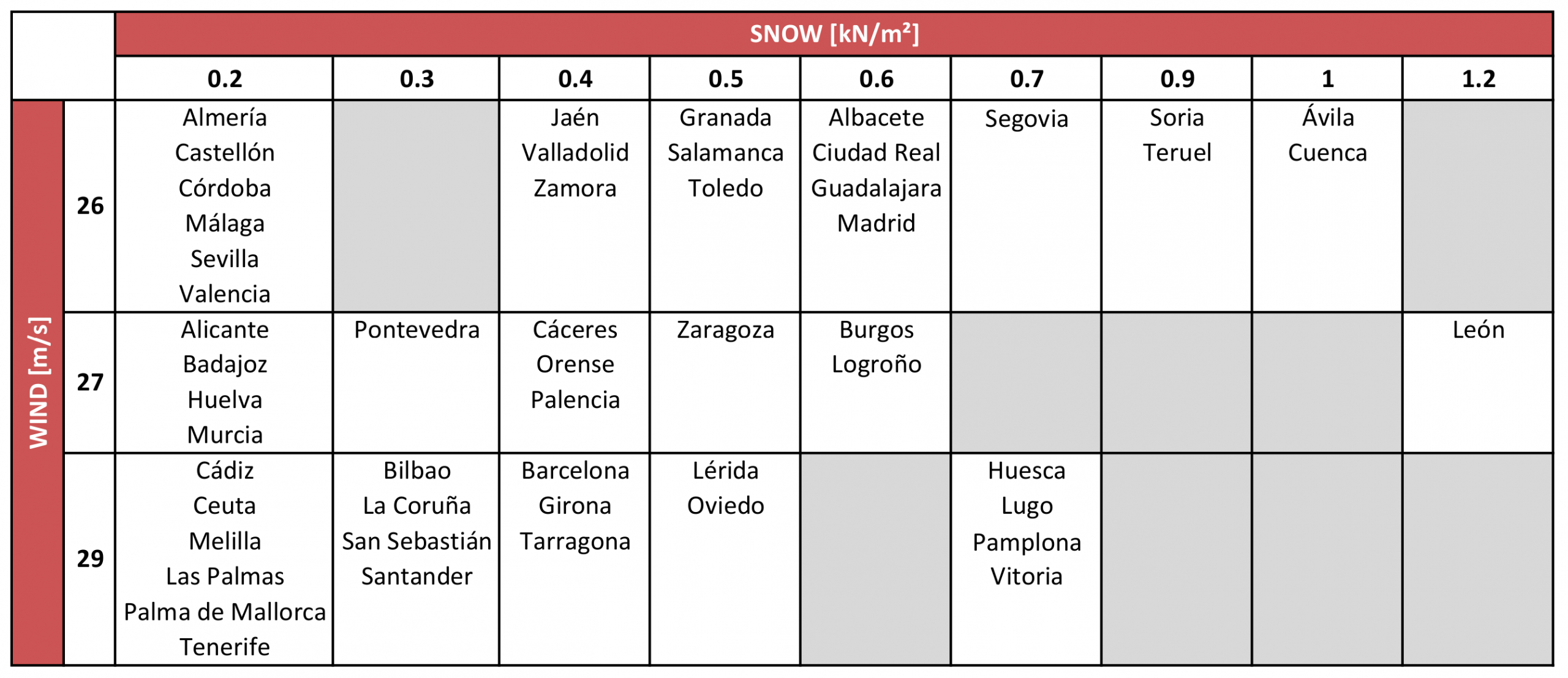
A configuration designed for a city defined in the table will be the same for the other cities in the same cell.
Conclusions
Carports with blocked wind flows should be studied in relation to the moments produced by suction winds, since they can cause unfavorable load states in the structure not considered in the design that leads to its collapse.
The relationships between wind and snow loads for each city of the Spanish territory define the configuration of structural profiles that would form the carport portal frame installed in this city, as well as their equivalence in other cities with the same wind and snow loads.
Finally, it should be noted that the Technical Building Code (CTE) is mandatory in Spain for the installation of carports, and any other building, to ensure the safety of people. The partial or total non-compliance of the same, in case of collapse of the structure, can lead to devastating consequences for civil and / or criminal liabilities on the project managers.
Related posts

Projects


About Us