Project Context
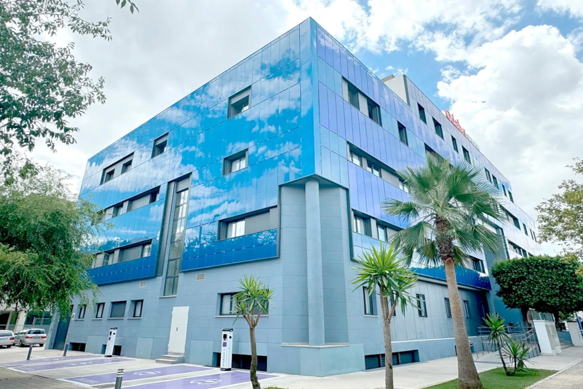
Architectural integration of solar energy is a massive trend, but it carries hidden risks without proper calculation. Anda Gestión Global S.L., manager of the Odalys Campus in Seville, detected visual anomalies in their panel installation after a period of operation. These visible deficiencies suggested a dangerous non-compliance with the Technical Building Code (CTE) safety standards.
Faced with this critical situation, a comprehensive PV facade structural validation becomes imperative. At Atreydes Engineering, we have assumed technical control of the situation. Our main goal is to determine if the installed configuration is safe for students and the building structure. To achieve this, we employ the advanced Finite Element Method (FEM) methodology.
This real case illustrates the vital importance of our structural calculation service to diagnose and prevent pathologies in existing buildings.
PV Facade Structural Validation Process
To execute a precise PV facade structural validation, we start by digitizing the real geometry. The panels are made of tempered glass. The largest format is 1800x600x10 mm, installed in a vertical position (portrait mode).
The fixing system is the neuralgic point of the assembly. The panels rest on vertical aluminum rails (alloy 6063-T5). They are held on their short sides by two aluminum clips screwed directly to the guides.
The load travels from the guides to the wall through L-shaped anchors. We secure the entire assembly with lag screws. If just one link fails, the entire PV facade structural validation will be negative. Below, we present the generated study model.
The unit must withstand its own weight and, above all, the wind load. On this specific facade, wind suction is more critical than compression. For safety, we base the calculation on suction.
In the FEM model, we use “shell” elements for the glass and L-anchors (constant thickness). We use “solid” elements for the complex guides. This precision is vital for a reliable PV facade structural validation.


Failure is not always a visible break; sometimes it is a permanent deformation that renders the part useless. In engineering, we distinguish between ductile behavior (deforms before breaking) and brittle behavior (breaks suddenly).
Ductile materials have a strain at break ( \epsilon_f ) > 0.05. Brittle ones are defined by their ultimate tensile strength ( S_{ut} ).
Ductile materials
For the PV facade structural validation regarding aluminum elements, we apply Von Mises ( \sigma_{VM} ). The component is safe if the stress does not exceed the yield strength reduced by a coefficient ( \gamma ):
\sigma_{VM} \leq S_y' = \Large \frac{S_y}{\gamma}
Where:
- \sigma_{MV} : Von Mises stress
- S_y : Yield strength
- \gamma : Safety factor (1.05)
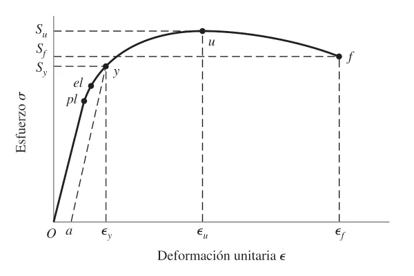
The Von Mises stress predicts when the material starts to yield plastically:
\sigma_{MV} = \sqrt{\Large \frac{(\sigma_1-\sigma_2)^2+(\sigma_2-\sigma_3)^2+(\sigma_3-\sigma_1)^2}{2}}
We assume a linear behavior (Hooke’s Law) to simplify the calculation in the elastic range:
\sigma = E \epsilon; \forall \epsilon < \epsilon_y
\epsilon_y = \Large \frac{\sigma_y}{E}
With:
- E : Elastic modulus
- \epsilon : Unit deformation
- \sigma : Stress
Where:
- S_y : Yield strength
- S_u : Ultimate strength
- S_f : Fracture strength
In 3D, the formula develops as follows:
\sigma_{MV} = \sqrt{\Large \frac{(\sigma_x-\sigma_y)^2+(\sigma_y-\sigma_z)^2+(\sigma_z-\sigma_x)^2+6 (\tau_x^2+\tau_y^2+\tau_z^2)}{2}}
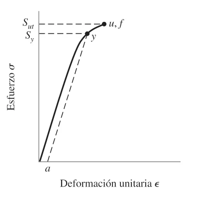
Brittle materials
Glass follows the maximum normal stress theory.
It fails if \sigma_1 \geq S_{ut} or \sigma_3 \leq -S_{uc} .
In our PV facade structural validation, we verify the tempered glass with:
\sigma_{MV} \leq \Large \frac {1}{\gamma} \normalsize min (S_{ut}, S_{uc})
Where S_{ut} and S_{uc} are the ultimate tensile and compressive strengths.
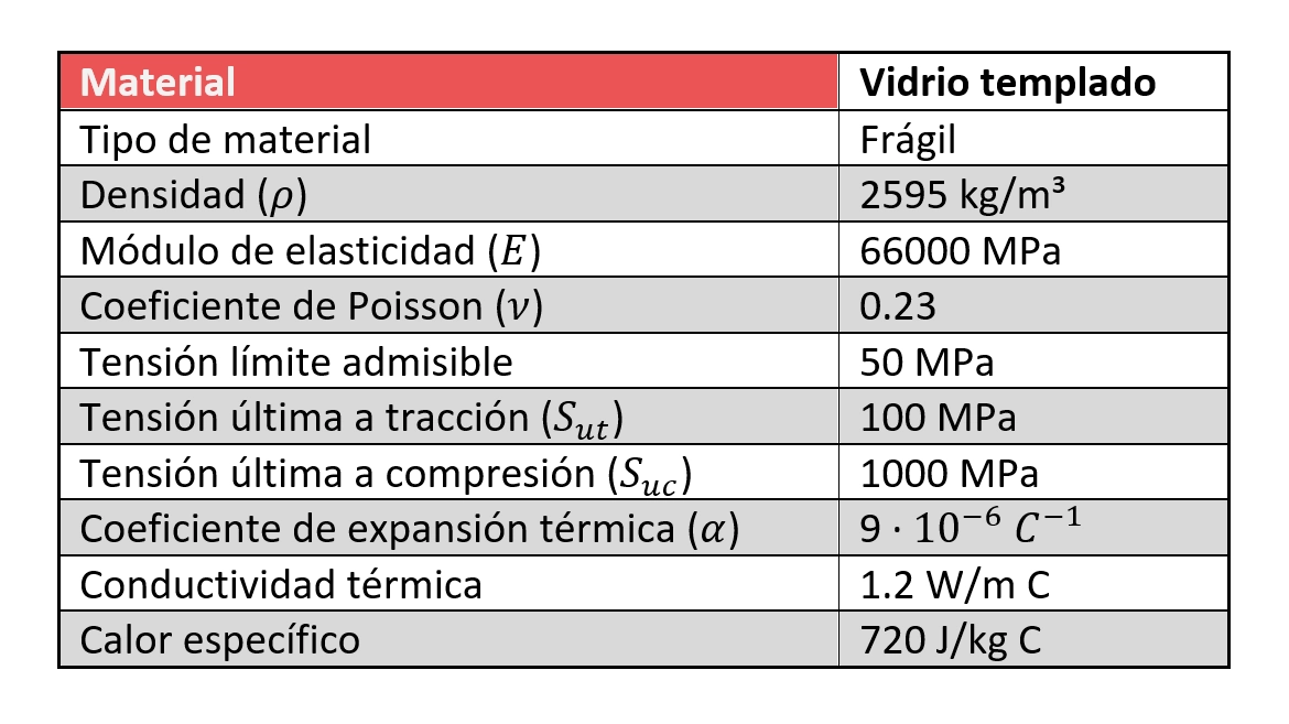
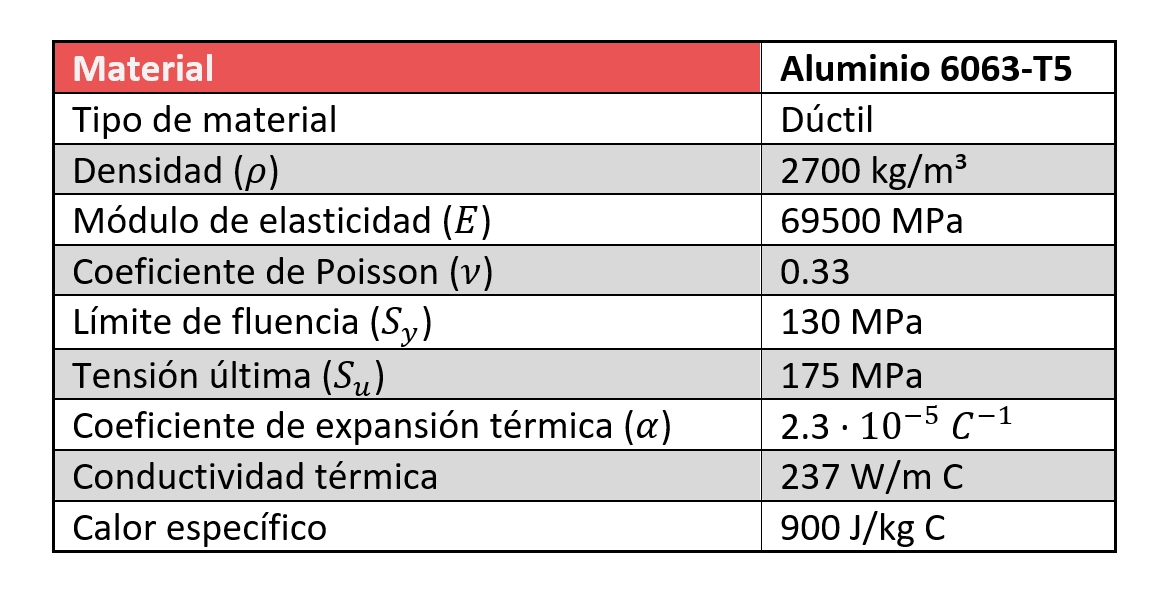
The quality of materials is fundamental for the success of any PV facade structural validation. In this specific project we analyze:
- Aluminum 6063-T5: Structural element (guides, clips, anchors).
- Tempered Glass: Solar capture element.
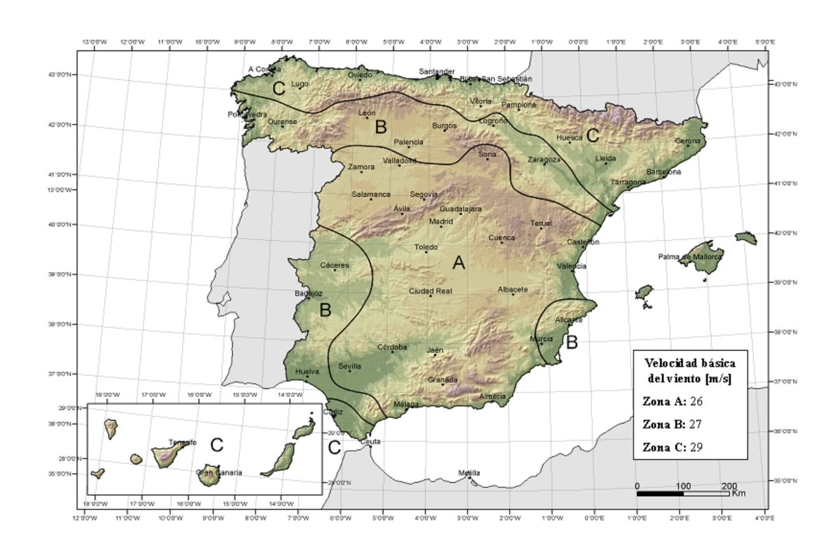
Besides its own weight, the determining load is the wind. For the calculation, we strictly apply the Technical Building Code (CTE), which is the standard regulation in Spain.
Calculation according to CTE
The basic wind speed ( v_b ) in Seville is 26m/s.
The dynamic pressure ( w ) is calculated as:
w = q_{ref} C_e(z) C_p
Where q_{ref} = \Large \frac{1}{2}\normalsize \rho v_b^2 with air density 1.25kg/m³.
The exposure coefficient ( C_e ) for 18m height in terrain type IV is 2.20.
According to CTE table D3, for areas >10m², the suction coefficient ( C_p ) is -1.2. This value is more unfavorable than pressure (0.8).
Finally, we factor the load with a safety coefficient ( \gamma ) of 1.5. The final load applied in the PV facade structural validation is:


Analysis Results
The stress maps confirm the initial suspicions. Excessive bending is observed in the tempered glass. Although the glass resists, the serious problem lies in the fixings.
By holding the panels only by the short side, the load is not distributed well. The aluminum guides fail to transfer the effort to the wall through the intermediate anchors. This critically overloads the end anchors.
The zones in white color indicate that the elastic limit (yield) has been exceeded. This implies permanent deformation. In a rigorous PV facade structural validation, this is unacceptable. The clamping clips are insufficient to withstand the design wind suction.


Conclusions
The current configuration (vertical panels with vertical guides) violates the Technical Building Code (CTE). There is a real risk of collapse or severe damage to the fixings.
The technical solution involves changing the layout to horizontal. This would allow fixing the panels by their long side, reducing the span from 1800mm to 600mm. Thus, the load would be distributed among more anchor points homogeneously.
This study demonstrates that PV facade structural validation is indispensable before and during operation. A bad design compromises investment and safety.
If you have doubts about the integrity of your building, check other cases in our Project Portfolio. For an immediate expert diagnosis, contact Atreydes Engineering.