FEM Carports. Beam vs Solid elements
In this post, Atreydes Engineering presents the calculation of a common portal frame for parking canopies using programs with beam elements and programs with solid elements. Both calculation methods are based on finite elements (FEM), but traditionally FEM calculation has been associated with a more complex geometry where discrete elements divide the bodies under study into smaller parts, usually tetrahedral in space (solid elements) or on a two-dimensional surface (shell elements).
Beam-type software
The design software for beam elements, since it has the CTE integrated, analyzes all possible hypotheses of this standard. If any element of the structure exceeds the elastic yield strength, it is marked in red color. In our example, pillar and beam formed by an IPE200 made of S275 steel, would fulfill the CTE guidelines.
The beam utilization ratio is 66% and 69% for the pillar, which leads us to think that these profiles can be lowered by one size, an IPE180, to make the portal frame more economical under these load conditions.
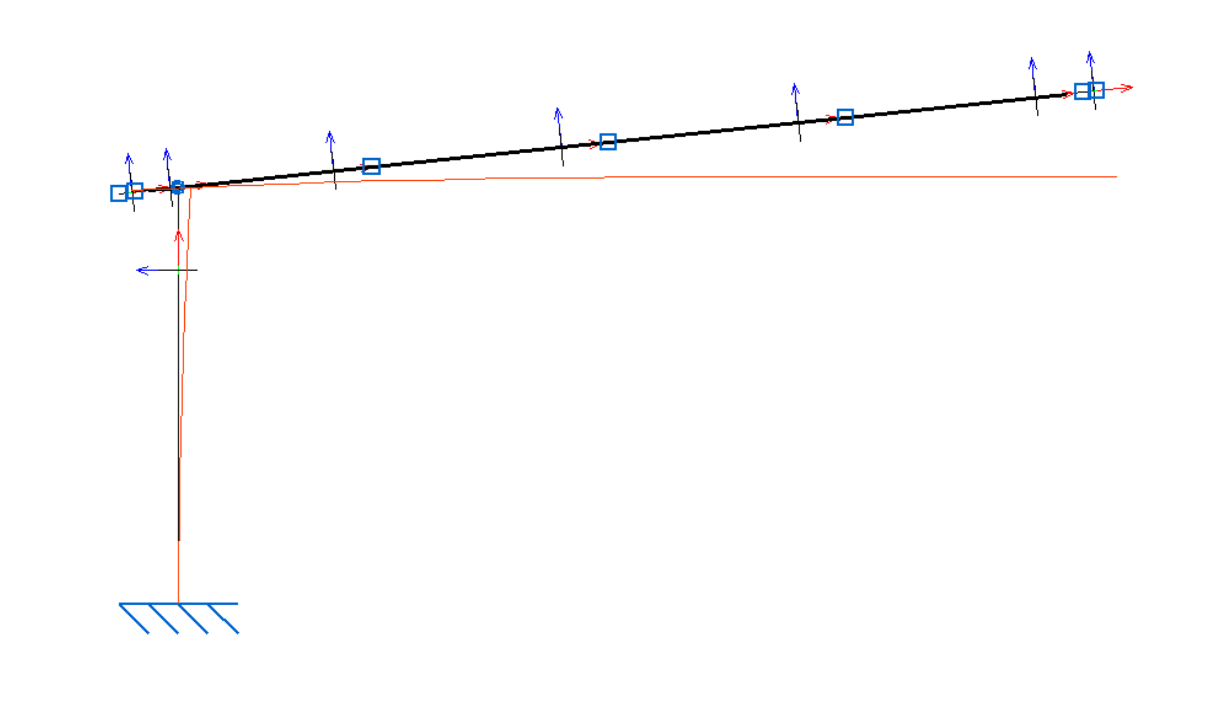
The maximum deflection occurs at the end of the beam furthest from the pillar with a value of 148 mm.
Solid-type software
Solid elements software, unlike the design software for beam elements and not having integrated the CTE standards, must be given as input the specific load hypotheses to be analyzed, in our case, the one described in previous paragraphs:
1.35PP+1.35PM+0.9VP+1.5N
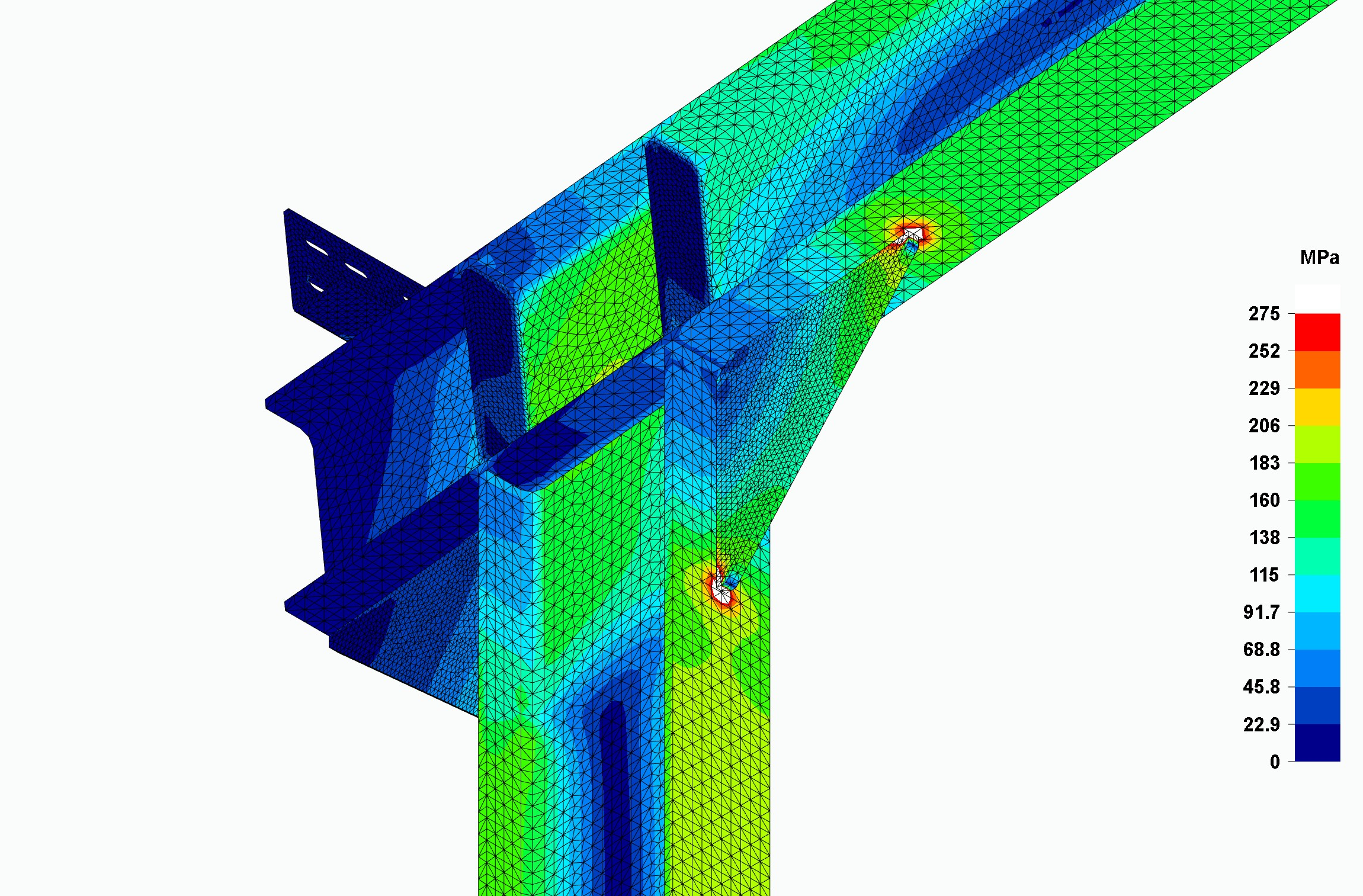
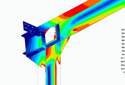
In a FEM analysis software, there is no utilization ratio as described as in beam element programs, since stress concentration sinks are created especially at abrupt changes in geometry, which distort this utilization. These are points or edges where the stress gradient grows very rapidly and where someone without sufficient experience can assume that the elastic regime of the material is not being complied with. They are points of localized yielding but do not extend to the rest of the structure and have no real influence on the structural performance. The analyst must skip them, and carefully ignore them, since, like any numerical simulation, the software must assign high values at these points in order to reach convergence. It should be noted that, in the analysis, only the elastic regime of the material is taken into account and that when the yield limit is exceeded, the stress-strain relationship of the material changes as it reaches the plastic regime, a regime that is generally ignored in these FEM analysis programs.
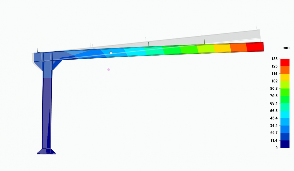
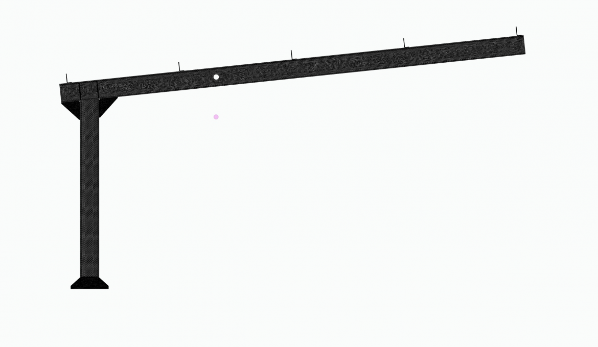
In this case, the maximum deflection is 136 mm.
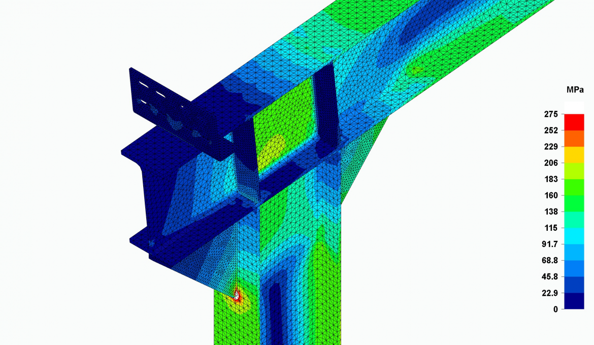
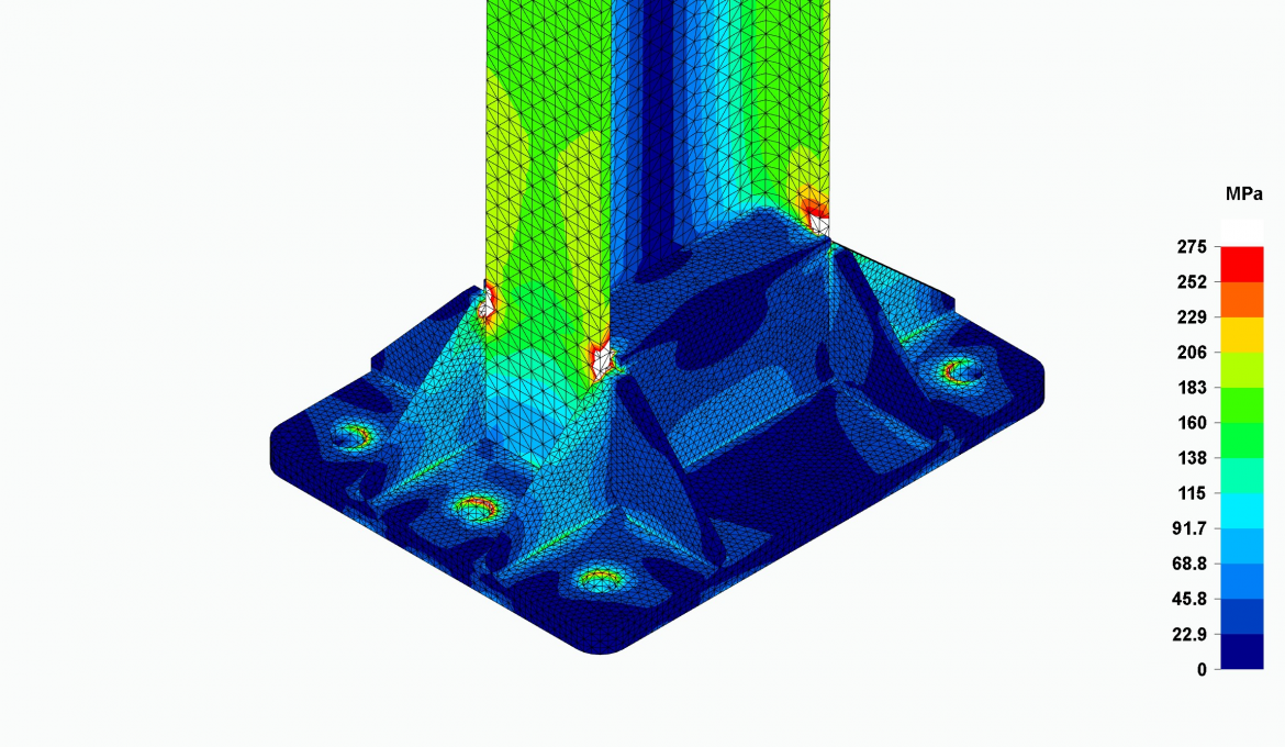
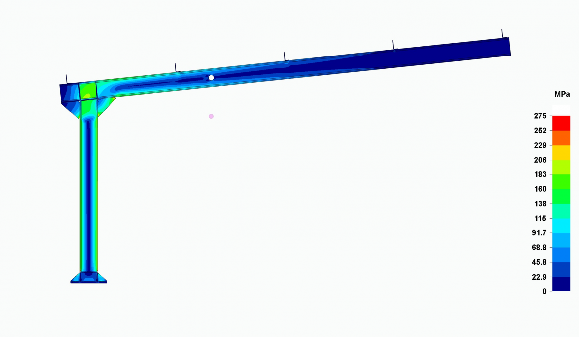
Small white areas in the images mark where the material stresses exceed its yield limit. As can be seen, they are very localized at very specific geometry changes, but do not affect the function of the portal frame. At these points there are usually important weld beads that reinforce these points of localized yielding.
Loads for this canopy are given according to the Technical Building Code (CTE) for self-weight, wind and snow at the Seville location, with a basic wind speed of 26m/s and a basic snow load of 0.2 kN/m². It will be assumed that the canopy allows wind flow through it without any restriction, such as a wall, and since the canopy has a slope of 6 degrees, CTE gives us a suction wind exposure coefficient (Cp) of -0.7.
Cada pórtico soporta una superficie de 5 x 5 metros de chapa con 5 correas en los apoyos diseñado para ello. Suponiendo un reparto equitativo en cada uno de estos apoyos, la carga en cada uno de estos apoyos será:
| Loads | Value [N] |
|---|---|
| Own weight (PP) | (*) |
| Dead loads (PM) | 450 |
| Pressure wind (VP) | 1130 |
| Suction wind (VS) | 1980 |
| Snow (N) | 1000 |
(*) Computed by the calculation software itself
Hipotheses of loads
CTE provides the different load hypotheses that must be considered to guarantee the safety of all structures. For our case, we will analyze the combination that provides the maximum moment at the pillar base which, finally, will be the one that provides the maximum stress in the structure. In this load hypothesis, the pressure wind and the snow have the same downward direction, adding their effect, together with the combination coefficients provided by the standard, to the increase of the moment at the pillar base.
The considered load combination is described below:
1.35PP+1.35PM+0.9VP+1.5N
While the connection points of parts (nodes) are represented as rigid or articulated points in programs using beam elements, the connections in calculation programs using shell and solid elements can be modeled in detail in all three dimensions.
Nodes in concrete structures can be considered rigid, since, being large cross-section and depth elements composed of concrete with steel reinforcement, they cannot rotate significantly with respect to each other. In steel structures, on the other hand, nodes are usually articulated, since the steel has the flexibility to rotate with the small section pieces that make up the nodes.
Sometimes in the calculation, it is absolutely essential that a node is modeled as rigid because a beam element program could interpret that joint as a mechanism if it were articulated, failing in its calculation.
If we consider rigid nodes in the calculation of structures through softwares with beam elements, in reality these must be reinforced to match the calculation simulation. If this is not the case, the calculation could reflect more favorable situations than in reality, which could lead to the collapse of the structure under certain load states.
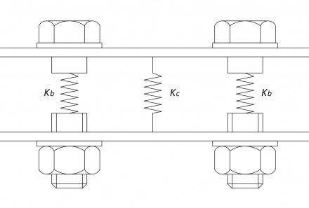
In structures where the rotation of the components that form a node is important, programs that use beam elements start to lose accuracy in the calculation, because it is difficult to establish the node stiffness to know the rotation between the parts. At this point, programs using shell and solids elements are more accurate, since, by modeling the geometry of the node more accurately, they also do so by establishing its stiffness.
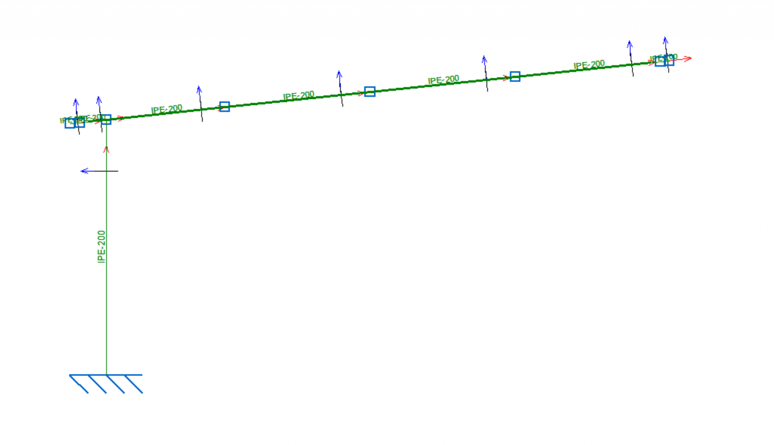
The portal frame consists of a 2 m high pillar with an IPE200 section that supports a 4.95 m long beam with the same section as the pillar and 6 degrees of angle above the horizontal. The material used in these sections is S275 hot rolled steel.
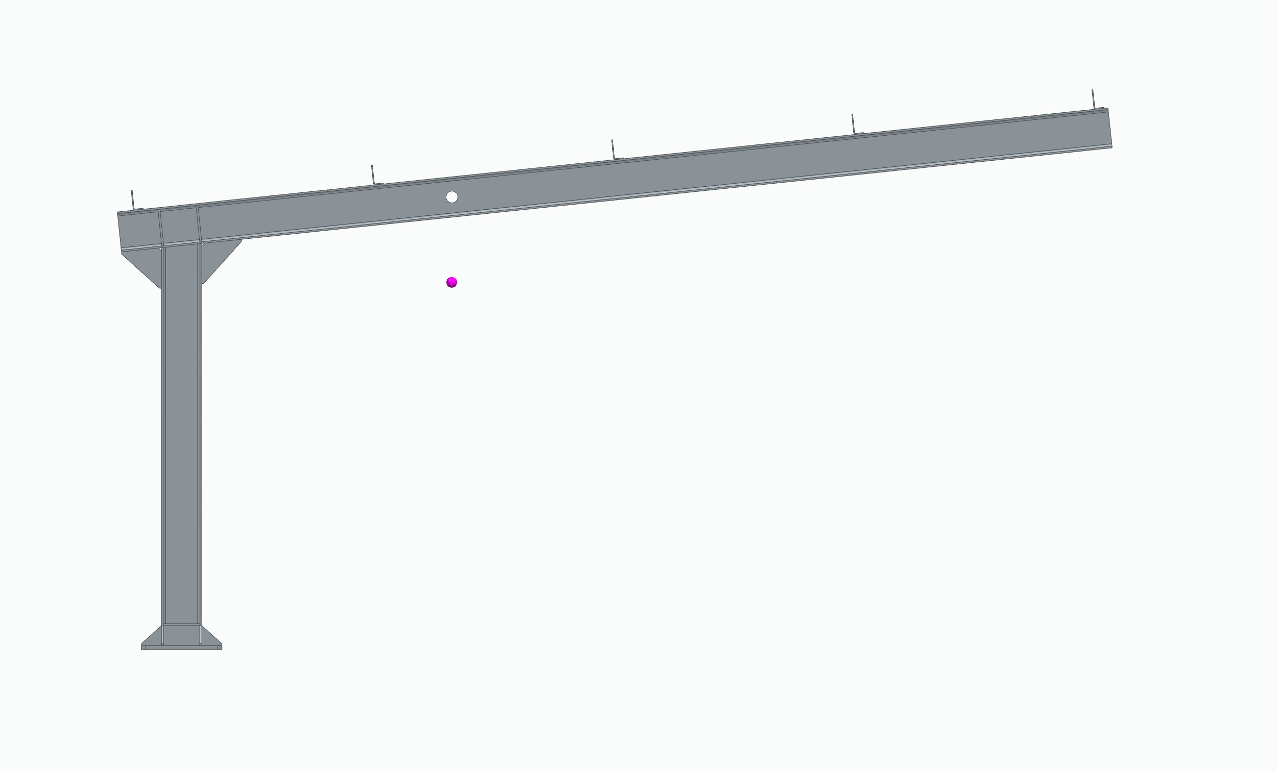
Beam-element modeling for portal frame is shown below:
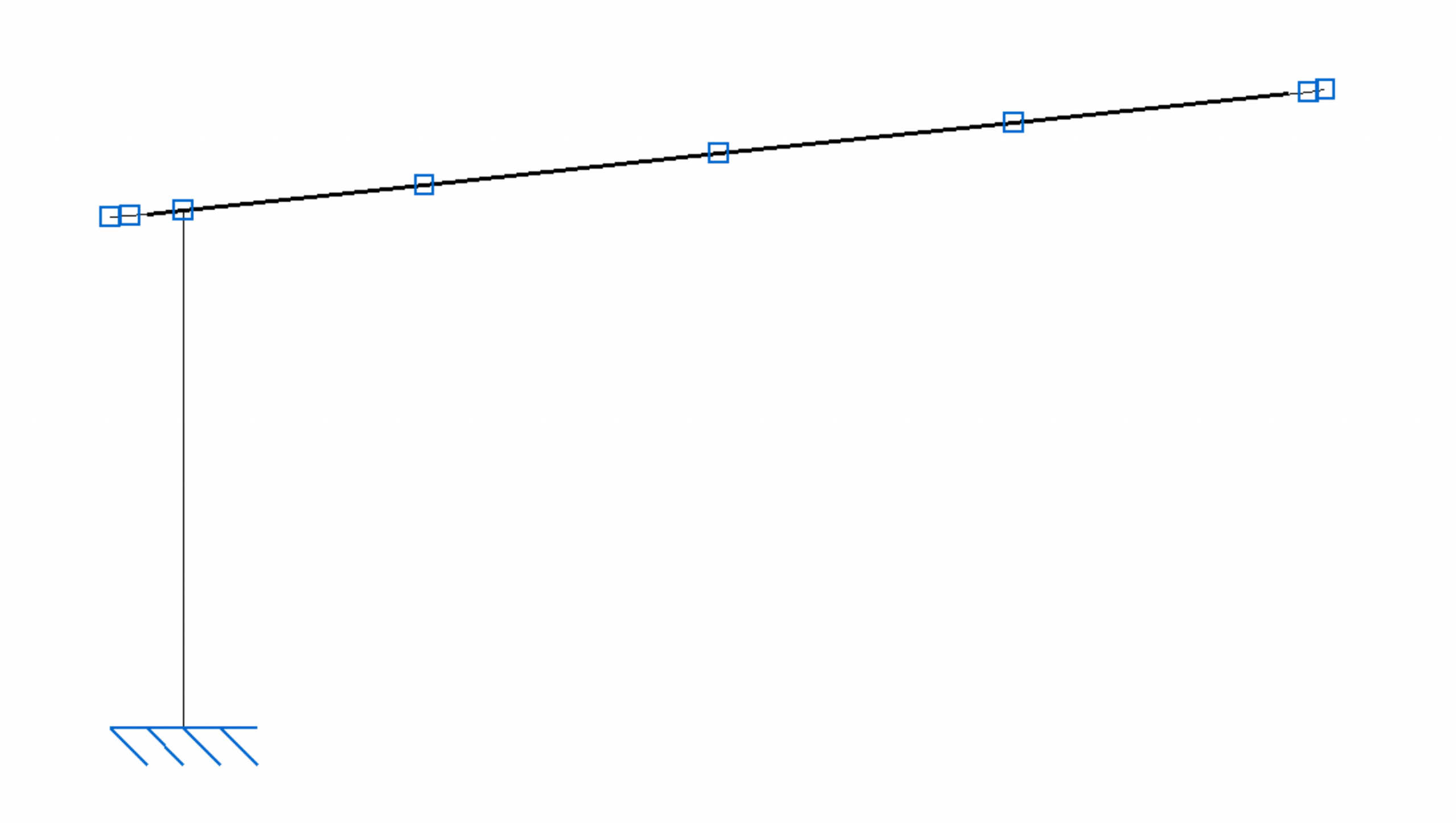
There are two nodes in the portal frame. The first one connects the pillar to the foundation, the second one connects the beam to the pillar. For beam type software, both must be modeled as rigid, since, if they are modeled as articulated, the parts that compose the structure could freely rotate between them, becoming a mechanism, and thus interrupting the calculation. It is possible to assign an intermediate stiffness to the node, but without real joint information any beforehand stiffness would validate the calculation, but it could be far from reality. For this reason, it is chosen to model these nodes as fully rigid.
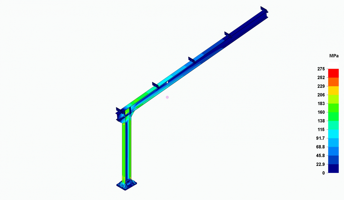
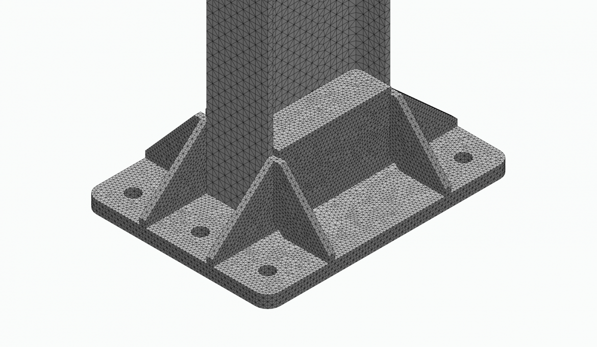
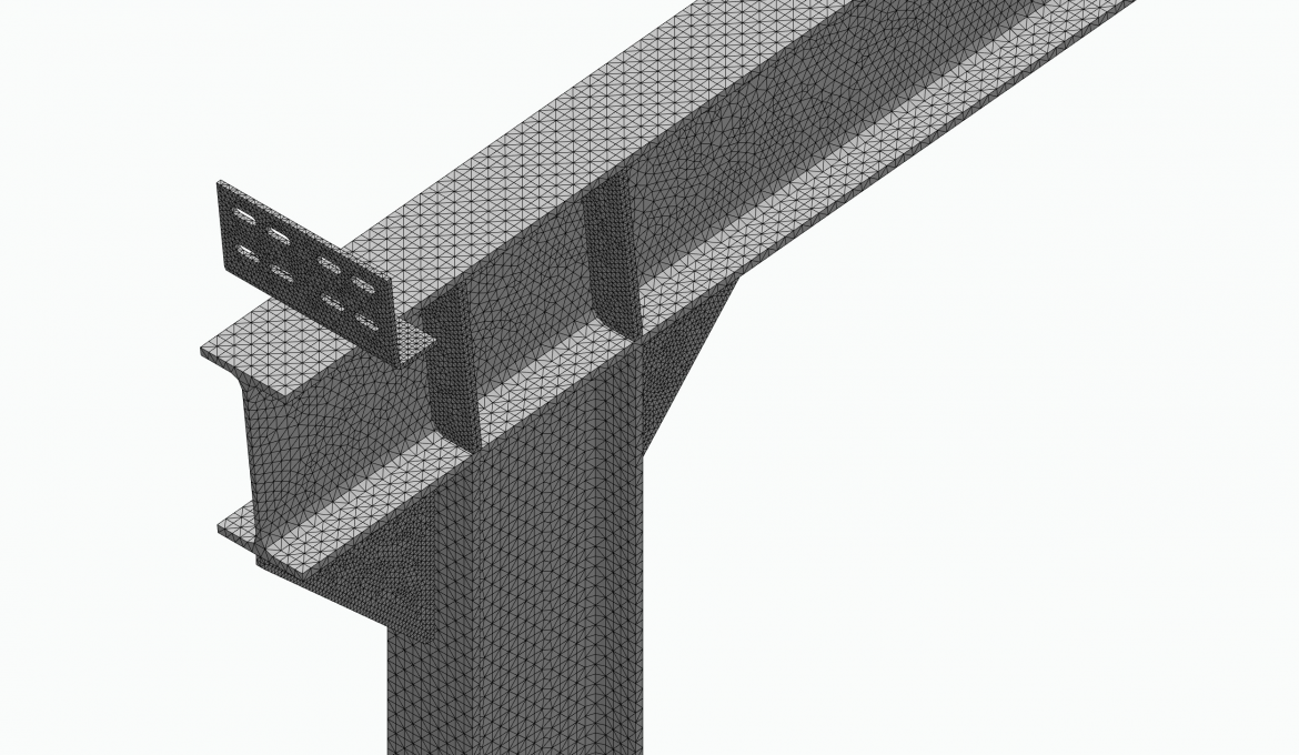
Solid modeling, on the other hand, can model both nodes very close to the reality, providing more accurate values of their stiffness and, therefore, more accurate values in the design parameters mainly in stress and strain of the material.
The joint design at the nodes can be done in several ways, as long as the elastic yield strength of the material under the described loads is not exceeded. In this post, Atreydes Engineering has proposed the following ones that can be observed together with their meshing:
Conclusions
The portal frame of a car canopy has been analyzed through two finite element method (FEM) calculation programs, one working with beam-type elements and the other with solid elements, taking into account the loads dictated by the Spanish Building Technical Code (CTE) for the location of Seville.
Both programs express equivalent maximum strains: 148mm for the program working with beam elements and 137mm for the program working with solid-type elements.
Regarding stresses, the program with beam-type elements shows that the yield limit is not exceeded under the loads proposed by the CTE in the sections of the structures. The program with solid-type elements shows zones of localized yielding that exceed said elastic limit at some points of the geometry, which, as we have already explained, should be skipped as they are theoretical stress singularities for the calculation convergence that, furthermore, do not exactly represent the reality in the structure under study.
Related posts
Projects


About us