Suction sail design
In the 80’s, Jacques Cousteau, developed several patents on the performance of autonomous sails to propel ships by means of wind energy. The idea is based on aspirating the flow that emerges in the trails of a cylindrical structure towards the interior of it to avoid the boundary layer separation. According to these patents, the lift force increases in the order of 6 times regarding the same body without this aspiration. If this force, which provides the lift, is oriented directly or partially with respect to the ship forward direction, it will be propelled in such direction, so a control system is necessary to orient the sail depending on the wind and the ship forward direction.
This idea was implemented in two autonomous sails on the ship Alcyone, and its design has remained largely unchanged to this day, partly because the efficiency of coal first, and petroleum derivatives later, did not accommodate new forms of shipping. Nowadays, where greenhouse gas emissions are questioned and the use of clean energies can be a way to reduce fuel due to a new more demanding international legislation, the wind propulsion of ships, displaced more than a century ago because of the rise of fossil fuels, gains a new meaning.

Functioning Principles
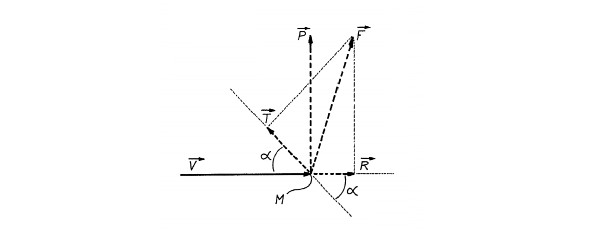
The following figure shows a device M such as a sail, placed in a fluid moving at a relative speed, v, with regards to this device, it is produced a strength, F, which decomposes into a lift force, P, perpendicular to the velocity, v, and a drag force, R, in the same direction as the velocity, v.

If the device M moves in one direction at an angle, α, with the velocity, v, it is subjected to a drive strength, T, which corresponds to the projection of the force F on this direction. It can therefore be seen that, for a given value of the angle α, the intensity of the drive strength T is the greater the higher the supporting force P and the lower the drag force R when α is less than 90 °.
Drag and lift are generally expressed by dimensionless coefficients Cd and Cl given by the following formulas:
\normalsize Cd = \LARGE \frac {R} { \small \frac 12 \normalsize \rho V^2 S}
\normalsize Cl = \LARGE \frac {P} { \small \frac 12 \normalsize \rho V^2 S}
Taking these expressions into account, it is seen that the fluid drive strength T is expressed by the following formula:
\normalsize T = \frac 12 \rho V^2 S (Cl \cdot sen \alpha - Cd \cdot cos \alpha)
This formula makes it clear that, for a given speed of the fluid, v, and for a given drive stress orientation α, this stress is the greater the higher the product S times Cz.
“Patent of invention 507,586. Improvements in a high lift force device to use the energy of moving fluids especially for the wind propulsion of ships. Fondation Cousteau. 11/30/1981”
Key aspects
Suction sail design integrates various technical areas such as aerodynamics, mechanics and automated control. Prioritizing some of these areas over the others will lead to optimized systems only in the prioritized aspect, leading to problems in the other areas which could be difficult to overcome, or, in extreme cases, impossible to solve technically. The different areas must work together, in a transversal way, to solve the requirements of scope, time and cost.
A heavy suction sail makes no sense as it detracts from the ship propulsion produced by its own weight. Optimization of a suction sail goes through the manufacture of its structure in aluminum. Aluminum must be protected against the sea salinity with paint according to marine standards. The construction of the structure requires the welding of this material which is more complicated than steel one, so the use of fabrication benches and robotic welding will guarantee the quality of the structure. The light weight of aluminum compared to other materials will reduce the inertial forces of the sail favoring the own stability and resistance.
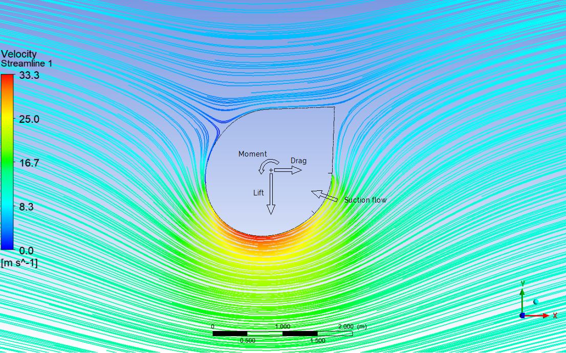
Cousteau proposed an elliptical design in the sail section where a mobile flap was positioned at the rear side to stabilize the outlet flow. This flap had to change its place to a symmetrical position depending on whether the wind was coming from port or starboard. He established an angle of attack with respect to the wind of 20º for a given suction flow, in which the sail reached a maximum lift coefficient to propel the ship. It should be mentioned that increasing the angle of attack with respect to the wind increments the suction flow rate to adhere the boundary layer in the trail, so that there is an angle of attack in which the flow cannot adhere or that the flow needed to adhere it is so great that it is not worth it or cannot be carried out. This suction flow rate is the higher the greater the incident wind speed. This caused Cousteau to limit its maximum suction flow to an angle of attack of 20º and a maximum incident wind speed of 10m/s.
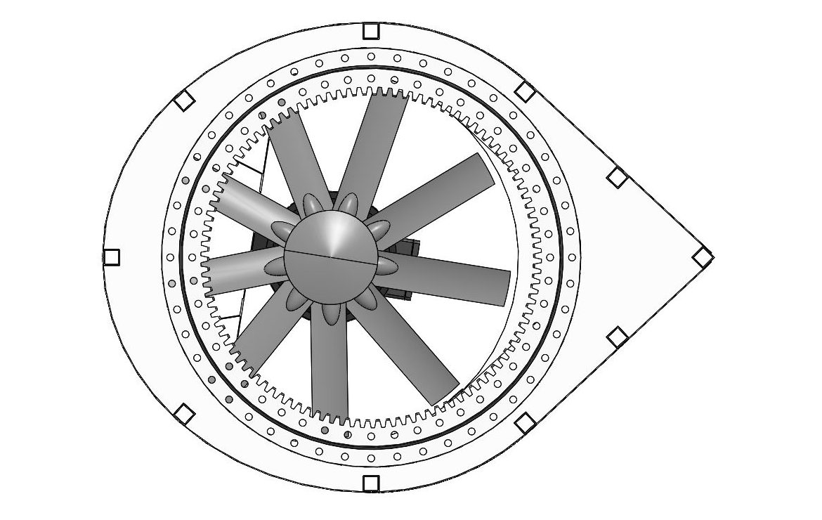
The elliptical shape of Alcyone sails has a primary axis of 2.05m and a secondary one of 1.35m, with an eccentricity of 0.66. This geometry allows an axial fan to be installed with a 1250mm diameter propeller that can give a maximum suction flow of 100,000 m3 / h, or what is the same, a maximum output of 34 kg/s for a 10m height.
Sail section geometry can be quickly optimized through CFD analyses comparing with Cousteau section where the influence of geometry shape, suction area and aspiration flow is studied to achieve higher lift coefficients.
There are currently two ways to characterize the aerodynamic performance of a body exposed to a wind flow: wind tunnel tests and CFD simulations.
In the case of suction sails, the Reynold number of the aspiration flow must be adjusted with that of the external flow. As the model is tested to scale, the holes in the sail suction zones, which are already small at full scale, become a problem as these holes become on the order of a few millimeters and are difficult to handle. They are also easy to clog, giving misrepresented results. This method is slow to optimize geometries since a different test model is needed for each proposed design.
CFD simulations, on the other hand, are a quick tool when creating alternative geometries and different design options, and results can be obtained quite fast when compared to wind tunnel tests and. Due to the suction flow difficulty in these tests, CFD simulations are the most suitable methodology for the geometry design of this type of sail.
To ensure that the wind sees the same geometry when it comes towards the ship from both sides, the aerodynamic profile must interchange the flap position and the suction surface.
Cousteau proposed a sail with 2 suction zones. Each one is sealed by the flap that changes its position depending on the side from which the wind attacks the boat. This presents to solve two coupled mechanical problems.
The first one is that the flap has to turn to adapt to the side from which the wind blows, the second one, and more important, is to seal one of the two suction area on which aspiration is not needed, since if part of the suction flow is lost, it may not adhere the boundary layer to the calculated value and therefore more flow is required to achieve this adherence, and the flow rate of the installed fans are limited.
On the other hand, the flap must be moved with mechanical components linked to the main structure of the sail. Being outside, it will support the wind and inertial loads, because of that, flap is a strategic component to take into account since it will introduce additional loads on the structure itself and guiding mechanisms. In addition, it must ensure the sealing of one of the suction zones through gaskets or other means that can be affected by the sea corrosion.
Current solutions go through considering a flap completely fixed to the structure, so the sail structure is greatly simplified to withstand the wind and ship inertial loads. Another advantage is the simplification of sail control since flap is not needed to move to change its position, so savings in mechanisms and motors are considerable. In return, geometry must be modified to optimize the lift coefficient that decreases in the order of 10% with respect to the Cousteau’s design and an increase in the suction flow that will be translated into an increase in the suction fan diameter which is totally acceptable.
In CFD simulations, the boundary condition that makes the boundary layer adhere is a mass flow rate of air coming into along the suction zone. But in fact, this is only possible if there is a pressure difference between the inside and outside of the sail through inlet holes for the calculated adhesion mass flow rate. This depression in the interior of the aerodynamic profile is achieved thanks to a fan which aspirate the air, that Cousteau placed in the upper part of the sail, through circular drill holes in the suction surface.
As it is not a constant pressure distribution along the suction line for a given section, suction flow through each of the holes will be different since in some you will find greater pressure than in others to pass from the outside to the inside, if we assume that the depression created by the fan is approximately constant. So, the flow through the holes will decrease where it finds the greatest external depression and will increase where this depression decreases. Viewing the static pressure graphs along the suction line, the flow rate will be lower in the holes away from the flap and will increase in the holes near the flap. The only thing which remains constant is the fan power.
Since high suction flow rates are needed to absorb the trail and adhere the boundary layer at high-medium pressures, axial fans seem the best option over radial ones, since the latter provide very high depressions at low flow rates. Axial fans rotate with a certain number of blades to achieve suction downstream of the impulse zone. Flow which they can move strongly depends on the radius of such blades, while the depression achieved depends on the number of blades and their angle of attack for a given rotation speed.
It must be taken into account that the depression given by the manufacturer for a design flow can be modified by the head losses found from the fan to the outside of the suction surface. If we have a fan in the upper part of the sail as in the Cousteau’s design, the pressure losses will be greater at the bottom. But the pressure drop that occurs through the grid in the suction surface is more important and, at the same time, difficult to determine. The pressure drop will be greater the smaller the hole diameters. If the hole is very small, the pressure drop created may be greater than expected and the fan may not be able to provide the necessary depression to adhere the flow, so the operating wind speed of the sail will have to be decreased to achieve lower depressions in the suction surface, or increase the diameter of the orifices so that the pressure drop is less. A representative full-scale test may be the best option to determine these pressure drops.


