Fluttering on single-axis solar trackers
With the rise and standardization of photovoltaic plants with single-axis trackers, competition among tracker manufacturers is becoming increasingly fierce. In order to supply ever more economical machines and structures, a reduction of the tracker material is often implemented, which results in a decrease of the stiffness and damping, which can lead to phenomena of fluttering on single-axis solar trackers that are often not predictable by means of classical calculations.
In this post, the parameters which influence the different aeroelastic phenomena of fluttering on single-axis solar trackers are introduced, as well as the guidelines for their analysis in wind tunnels, since they require the stiffness and damping of the tracker structure to observe the coupling of the aerodynamic forces to the equations that govern its response.
Oscillatory Motion
It is very likely that fluttering on single-axis solar trackers are associated with the only degree of freedom they have, since they use a very long and slender torsion tube to transmit their motion. Thus, we can stablish the vibration equation of the tracker taking into account all the forces acting on it:
\normalsize I_\theta \ddot \theta + c_\theta \dot \theta + k_\theta \theta = 0
Where:
- \normalsize I_\theta : polar moment of inertia
- \normalsize c_\theta : torsional damping
- \normalsize k_\theta : torsional stiffness
- \normalsize \theta : angular position for the tracker end section
- \normalsize \dot \theta : angular speed for the tracker end section \Large \frac {d\theta}{dt}
- \normalsize \ddot \theta : angular acceleration for the tracker end section \Large \frac {d^2\theta}{dt^2}
If there are no forces applied to the tracker, the sum of terms is equal to 0.
Two important parameters are defined below:
- Angular natural frequency (\normalsize \omega_n ): frequency [rad/s] at which the tracker vibrates in resonance.
\normalsize \omega_n = \sqrt {\Large \frac {k_\theta} {I_\theta}}
- Damping coefficient (\xi) : ratio between the system damping and the critical damping, the one that marks the beginning of the resonance.
\normalsize \xi = \Large \frac{c_\theta} {2 I_\theta \omega_n}
Therefore, the vibration equation can be expressed as:
\normalsize \ddot \theta + 2 \omega_n \xi \dot \theta + \omega_n^2 \theta = 0
The factor that multiplies \normalsize \dot \theta is known as the damping term, while the stiffness term accompanies \normalsize \theta .
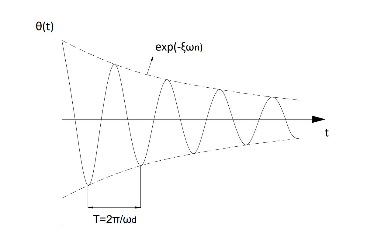
The solution to the differential equation of vibration, mathematically also called solution of the homogeneous equation is as follows:
\normalsize \theta (t) = \exp(-\xi \omega_n t) \left[A \cos(\omega_d t) + B sin(\omega_d t)\right]
Where A and B are constants which are defined with initial conditions, being ( \normalsize \omega_d ) the damped frequency:
\normalsize \omega_d = \omega_n \sqrt{1-\xi^2}
When other external forces are involved in the equation, other terms are added to this solution, but because this homogeneous equation represents the purely mechanical system, the tracker will have a part of its resonant response that will inevitably pass through the described solution.
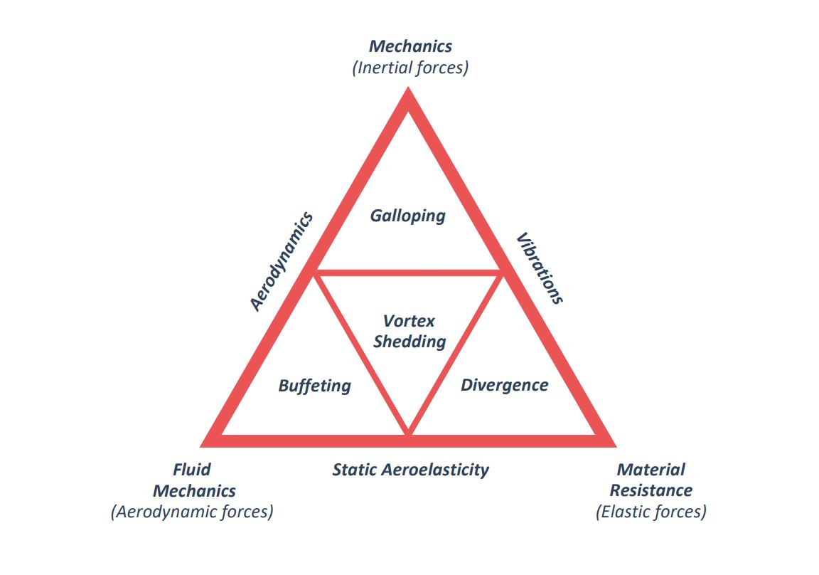
Fluttering is a characteristic phenomenon of aeroelasticity and was one of the first oscillations observed. Although these types of aeroelastic instabilities are typical of aeronautical structures, some may also appear in civil structures, especially if their sections are straight and elongated, bearing some similarity with the profiles of aircraft wings, like fluttering on single-axis solar trackers.
It must be said that there seems to be some confusion between the terms fluttering and galloping, especially if only one degree of freedom is involved in the instabilities; in general the term galloping is usually used when speaking of non-aeronautical structures, except if the fluttering is classical, where two degrees of freedom are implicated, which is occasionally applied to both types of structures.
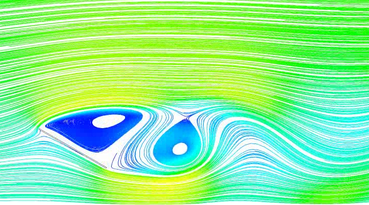
It is important to note that the oscillatory motion of a body that generates lift, as the oscillatory motion modifies the aerodynamic forces, if the flow is potential or near potential, by virtue of the theorem of the conservation of vorticity, vortices must necessarily be separated and dragged towards the wake and interact with the fluid flow around the body.
However, this type of vortex separation is completely different from that associated with the von Karman, since in this other mechanism the vortices detach by forming a vortex wake even though there is no transverse motion of the body.
The phenomena of fluttering on solar trackers which can appear are as follows:
Torsional Divergence and Galloping
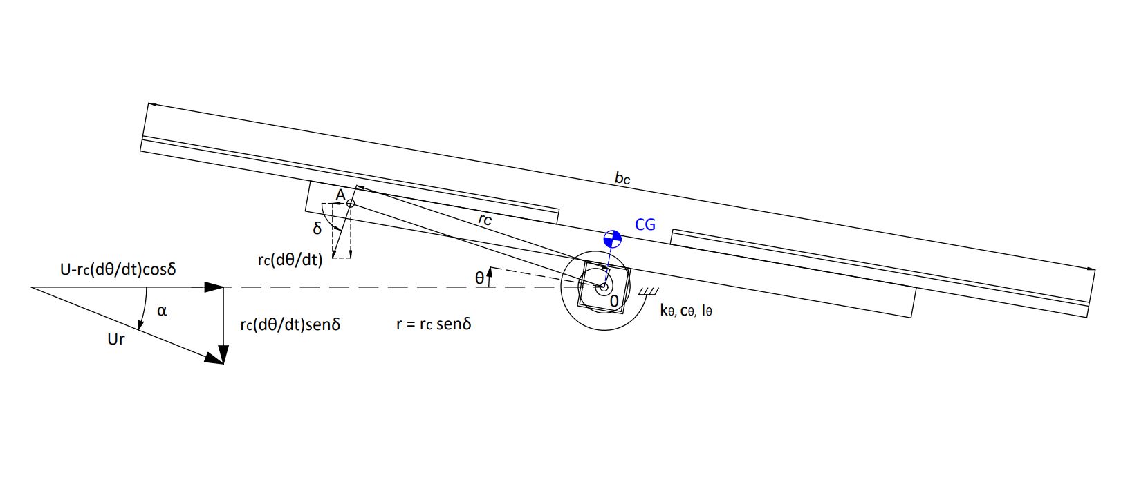
If we simplify the aerodynamic wind forces at point A on the tracker, the vibration equation is modified by the coupling of the dynamic forces due to the wind:
\normalsize I_\theta \ddot \theta + (2 I_\theta \omega_n \xi + \frac{1}{2} \rho U r b_c^2 \frac{\partial c_m}{\partial \alpha}) \dot \theta + (k_\theta - \frac{1}{2} \rho U^2 b_c^2 \frac{\partial c_m}{\partial \alpha}) \theta = 0
If we analyze the stiffness term, torsional divergence occurs when there is a velocity ( U_{cr}|_{div} ), which produces a coefficient \Large \frac{\partial c_m}{\partial \alpha} \normalsize > 0 that nullifies the system stiffness:
U_{cr}|_{div} \geq \Large \frac {1} {b_c}\sqrt {\frac {2 k_{\theta}}{\rho \frac{\partial c_m}{\partial \alpha}}}
If we analyze the damping term, the torsional galloping occurs when there is a critical velocity ( U_{cr}|_{gal} ), which produces a coefficient r\Large \frac{\partial c_m}{\partial \alpha} \normalsize < 0 that nullifies the system damping.
U_{cr}|_{gal} \geq \Large \frac {-4 I_\theta \omega_n \xi} {\rho b_c^2 r \frac{\partial c_m}{\partial \alpha}}
The functions expressing fluttering have the form of hyperbolas with the coordinate axes as asymptotes:
U_{cr}|_{div} \large (\frac{\partial c_m}{\partial \alpha})\normalsize^{(\frac {1} {2})} \normalsize \geq \Large \frac {1} {b_c}\sqrt {\frac {2 k_{\theta}}{\rho }} \normalsize = cte_1
U_{cr}|_{gal} \large (\normalsize r \large \frac{\partial c_m}{\partial \alpha}) \normalsize \leq \Large \frac {-4 I_\theta \omega_n \xi} {\rho b_c^2 } \normalsize = cte_2
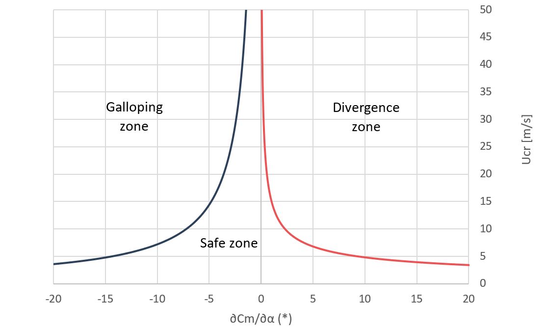
To delay the appearance of fluttering it is necessary to increase the absolute value of the constants, thus decreasing the curvature of the hyperbolas.
The simplification of representing the dynamic torsional performance by the aeroelastic response of a single point (A) on the body is excessive and, moreover, in a real configuration the oscillatory motion around the torsion axis gives rise to the separation of alternating eddies whose effect on the aerodynamic loads of the body cannot be predicted with a quasi-stationary model; but the dependence of parameters can be visualized for a qualitative analysis.
Vortex Separation & Buffeting
Structure oscillations induced by the separation of vortices are due to an effect of the resonance associated with the vortex configuration formed in its wake.
The vibration due to buffeting is that which is produced by turbulence or other disturbances of the flow not produced by the obstacle that suffers them, distinguishing two types of buffeting: the one generated by the turbulence of the incident wind flow itself and the one due to disturbances caused by some other nearby body located in the flow above the body under consideration. The latter is known as wake buffeting and can be found in the inner rows of trackers that make up a solar plant.
It must be said that, although the vibration induced by vortices and wake buffeting can be a potentially damaging phenomena (due to the fatigue involved in the application of alternating forces), the formation of a vortex configuration gives rise, however, to a stable oscillation, since the excitation energy has an infinite value for each particular frequency, which can be limited or eliminated by using damping devices, with the possibility of altering the excitation frequency to move it away from the own structure frequency.
Since the different forms of instability described can occur over a wide range of wind speeds, they are usually tested in low-scale wind tunnels, sweeping in speed while waiting for the appearance of such instabilities which will manifest themselves by means of large amplitude vibrations on the tracker torsion axis.
Analyzing fluttering on single-axis solar trackers requires to understand that the tracker mechanics and the dynamic wind loads are coupled, so the wind tunnel must replicate the vibration equation constants of the tracker at scale, since the dimensions of the tracker are also scaled.
For this purpose, 8 fundamental parameters are defined:
- \normalsize b_c : tracker characteristic length
- \normalsize \rho : air density
- \normalsize \upsilon : air kinematic viscosity
- \normalsize U : test wind speed
- \normalsize \theta : incidence angle
- \normalsize I_\theta : tracker inertia
- \normalsize \omega_n : tracker natural frequency
- \normalsize \xi : tracker damping coefficient
Given that a wind tunnel is made to scale, the dimensionless parameters between the scale of reality (r) and the scale in the wind tunnel (m), it must be fulfilled:
\normalsize Re = \Large \left[ \frac {b_c U}{\upsilon} \right]_r \normalsize = \Large \left[ \frac {b_c U}{\upsilon} \right]_m
\Large \left[ \frac {U}{\omega_n b_c} \right]_r \normalsize = \Large \left[ \frac {U}{\omega_n b_c} \right]_m
Since the characteristic length ( b_c ) in reality is much greater than that in the wind tunnel, the velocity must be greater in the wind tunnel so that the Reynolds number (Re) is maintained. But, in most cases, this will not be possible because wind tunnels have a maximum velocity that they cannot exceed by design. Given that they are angular geometries, it can be verified that the pressure coefficients on this type of structures do not vary with the Reynolds number, since the boundary layer separates quickly, so it is only necessary that, in the wind tunnel, the Reynolds number is higher than the critical ( 10^5 ) to ensure that it is within the turbulent flow.
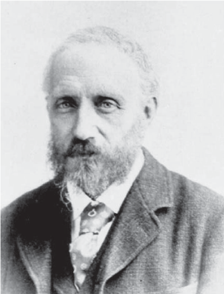
Osborne Reynolds
(Belfast, 1842 – Watchet, 1912)
Irish engineer and physicist who analyzed the change from laminar to turbulent regime inside pipes. As a result of these studies in 1883, he defined the Reynolds number (Re), which establishes the relation between inertial and viscous forces.
It must also be ensured that the range of reduced velocities ( \Large \frac{U}{\omega_n b_c} ) is consistent with the values of the eigenfrequencies and the design velocity of the full-scale tracker. It is important to note that many times the stiffness chosen for the tracker in the tunnel will not match with the real one in scale, so the frequency will have to be scaled with an amplification or reduction factor so the wind speed under test would also be affected by this issue.
Finally, whether a wind tunnel reflects results close to reality will depend on whether the relative stiffness and damping values of the tracker are correct. These data must be approximated in design and corroborated by a prototype, as they are difficult to establish, especially those related to damping, so they are usually tested with several values of this parameter.
The result is usually a map of values between the tracker tilt angle ( \theta ) and the critical speed ( U_{cr} ) at which the instability starts for different wind directions.
Related posts

Projects


About us