Turbosails vs. Rotorsails
With rising fuel prices and new legislation to reduce the emission of greenhouse gases, shipping companies are looking for alternative solutions to help them save fossil fuels.
During the 20th century, wind-based technologies were developed for the propulsion of vessels that obeyed the principles of airfoil lift, which are becoming more and more meaningful nowadays. These are called WAPS (Wind Assisted Propulsion Systems).
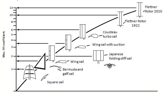
The following figures show the different technologies listed in DNV standard ST-0511, in addition to their lift coefficients:
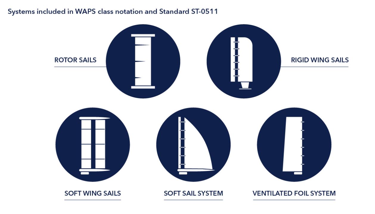
These technologies seek to generate the maximum possible propulsion force through the wind on a vertical structure (rigid sail) that, aligned with the direction of the vessel motion, reduces fuel use in the overall engine of the ship.
There are technologies based on airfoils with low lift coefficients and a large surface area exposed to the wind to produce the propulsion force. Others have a small surface area, but with a high lift coefficient that is achieved by means of an active mechanism to adhere the boundary layer that surrounds the rigid sail geometry.
The latter, the Flettner rotors and the suction sails or turbo-sails, arranged in the upper part of the figure due to their high lift coefficient, are the most promising because, if we compare them with the other technologies, they are capable of generating a greater force at the same dimensions or, from another point of view, they generate the same force with a much smaller area exposed to the wind, so the reduction of material and weight is very significant in them, which gives them many advantages and makes them very competitive.
On the other hand, they need additional power to adhere to the boundary layer of the wind flow that surrounds them in operation, so that if this adherence is not achieved, the lift coefficient drops drastically and, not having a considerable surface area, the propulsion force produced drops in the same way.
Aerodynamic principles of lift
Aerodynamics is the part of fluid mechanics that studies fluids in motion and the forces or reactions to which bodies immersed in them are subjected.
Daniel Bernoulli experimentally proved that “the sum of pressure and velocity at any point remains constant in a fluid in motion”. Therefore, for this constant to be maintained, if a particle increases its velocity, it will be at the cost of decreasing its pressure and vice versa.
Bernoulli’s theorem is usually expressed as follows:
P_t = P_e + P_d = P_e + \Large \frac{1}{2} \normalsize \rho V^2 = cte
Where:
- P_t : total pressure
- P_e : static pressure
- P_d : Dynamic pressure
- V : fluid speed
- \rho : fluid density
Therefore, if we place a flat object slightly inclined upwards against the wind, it will produce lift. An airfoil is a body that has a specific design to take maximum advantage of the forces that originate from the variation of velocity and pressure when this airfoil is placed in an air stream.
Airfoils can be applied in maritime navigation to propel vessels, so that they are installed vertically on the ship in such a way that they can rotate or orient themselves to the wind with respect to the ship’s direction of motion. When an airfoil is subjected to an air flow, such as the wind, a resultant aerodynamic force appears, which varies depending on its angle of attack. This can be divided into the aerodynamic lift ( F_l ) and drag force ( F_d ).
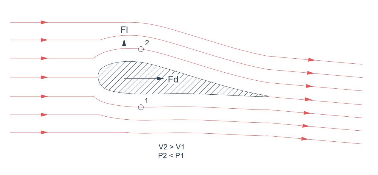
Lift ( F_l ) is the force developed by an airfoil as it moves through a fluid as a difference of pressures exerted on its geometry and whose direction is perpendicular to that of the fluid. As with other airfoil forces, in practice, dimensionless coefficients are used to represent the effectiveness of the body shape to produce certain forces and are used to facilitate calculations, designs and comparisons between airfoils.
The lift force F_l ) is defined as the integral of the pressure and friction forces extended over the entire surface of the airfoil perpendicular to the wind direction.
F_l = \oint_S (p-p_0) n_y dA + \oint_S (\bar{\bar{\tau}} · \vec{n})_y dA
Likewise, drag force ( F_d ) is defined as the integral of the pressure and friction forces extended over the entire surface of the airfoil parallel to the wind direction.
F_d = \oint_S (p-p_0) n_x dA + \oint_S (\bar{\bar{\tau}} · \vec{n})_x dA
Since these integrals are difficult to solve analytically, airfoils are tested in wind tunnels to extract a dimensionless coefficient to replace these integrals. Thus, the lift coefficient ( C_l ) and drag coefficient ( C_d ) are used to compare the lift and drag forces quickly and intuitively between different airfoil geometries without having to take into account the fluid velocity or the size of the airfoil geometry. For this reason, any geometry can be scaled to be measured in a wind tunnel, it simply has to conserve its shape, but not its size.
Turbosail
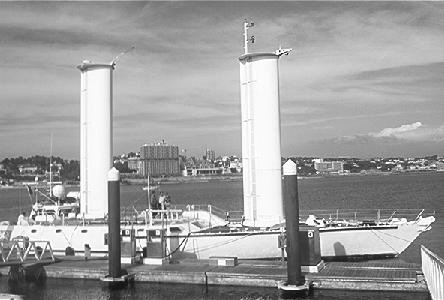
In the 1980s, Jacques Cousteau developed the turbosail inspired by flettner rotors. This rigid sail has a cylindroid shape and avoids the boundary layer separation by partial suction of flow on the leeward side through two perforated surfaces. It has a movable flap that changes its position symmetrically if the wind is coming from port or starboard to drive the direction of lift towards the forward line of the vessel, which also provides sealing on the perforated surface that is not working.
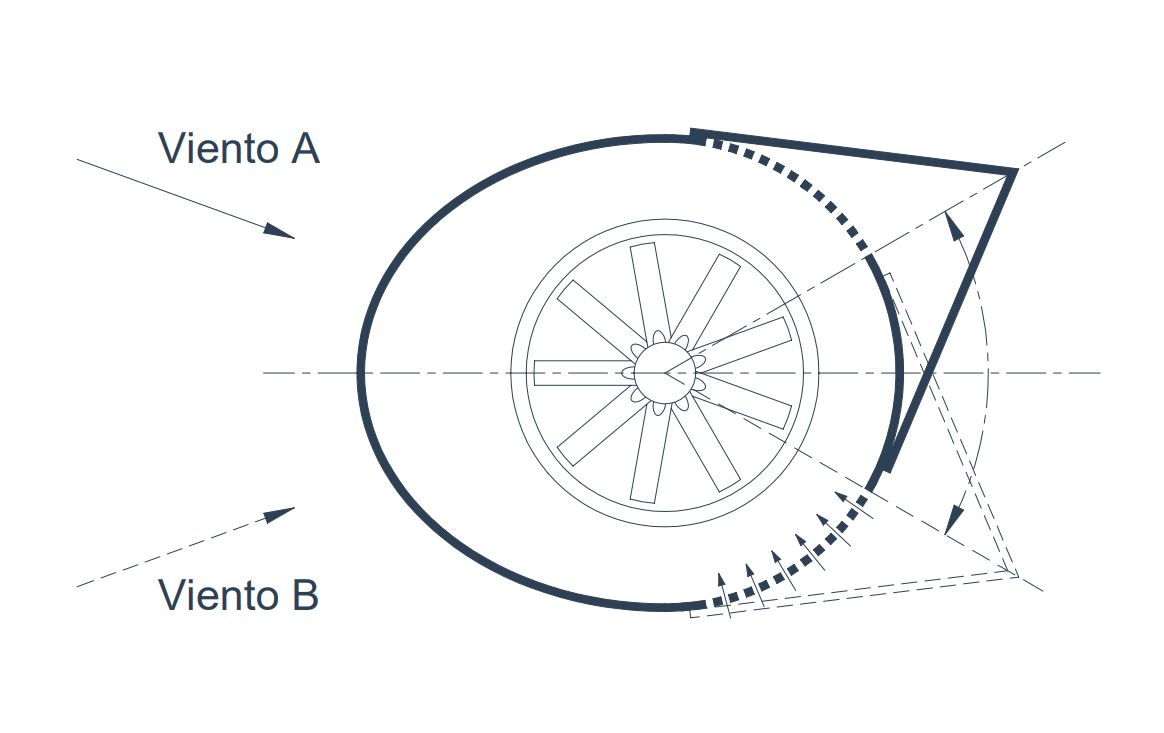
In a cylindroid body exposed to the wind, the boundary layer separation occurs at a certain point on the surface, which depends mainly on the flow characteristics and the Reynolds number. If part of the flow is aspired through the leeward perforated surface by means of a flow rate ( Q ), the main flow adheres and increases, therefore, the lift force ( F_l ) by means of an increment of its dimensionless coefficient ( C_l ), which reaches values around 6 when adherence begins.
Cousteau installed two turbosails on the 31-meter length ship Alcyone with the following characteristics:
- Characteristic length ( L_c ): 2.05m
- Height ( H ): 10.2m
- Vacuum power: 18kW
For Cousteau’s turbosail section, the graph that relates the lift coefficient ( C_l ) with respect to the suction one ( C_Q ) is shown below, according to these two dimensionless parameters:
C_Q = \Large \frac {Q}{V L_c}
C_l = \Large \frac {F_l}{\frac{1}{2} \rho V^2 L_c}
Where:
- Q : suction flow rate [m³/s]
- V : wind speed [m/s]
- L_c : characteristic length [m]
- F_l : lift force [N]
- \rho : air density [kg/m³]
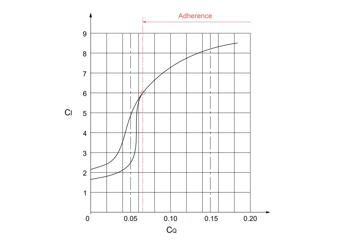
This type of sail has the particularity that considerable Cl is reached from a certain CQ. If this minimum flow rate is not reached, the lift coefficient drops significantly.
Excluding the three-dimensional aerodynamic losses, it is found that, for the Cousteau’s turbosail working with an average wind of 10m/s, the flow rate necessary to achieve the adherence of the main flow through the entire perforated surface is:
Q = V L_c C_Q H = 10 · 2.05 · 0.064 · 10.2 = 13.4 \large \frac{m^3}{s}
With H as the suction head, which is made to coincide with the sail height and assuming that the suction flow is the same for all sections of that height.
To this suction flow Q corresponds the following lift force:
F_l = \Large \frac{1}{2} \normalsize \rho V^2 L_c C_l H = \Large \frac {1}{2}\normalsize 1.225 · 10^2 · 2.05 · 6 · 10.2 = 7684N
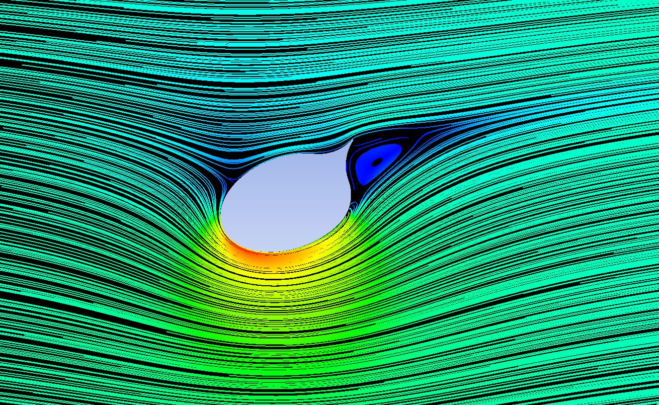
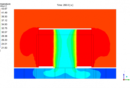
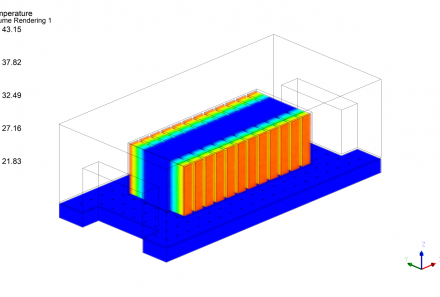
A CFD simulation of Cousteau’s sail section working without and with suction flow rate is shown below.
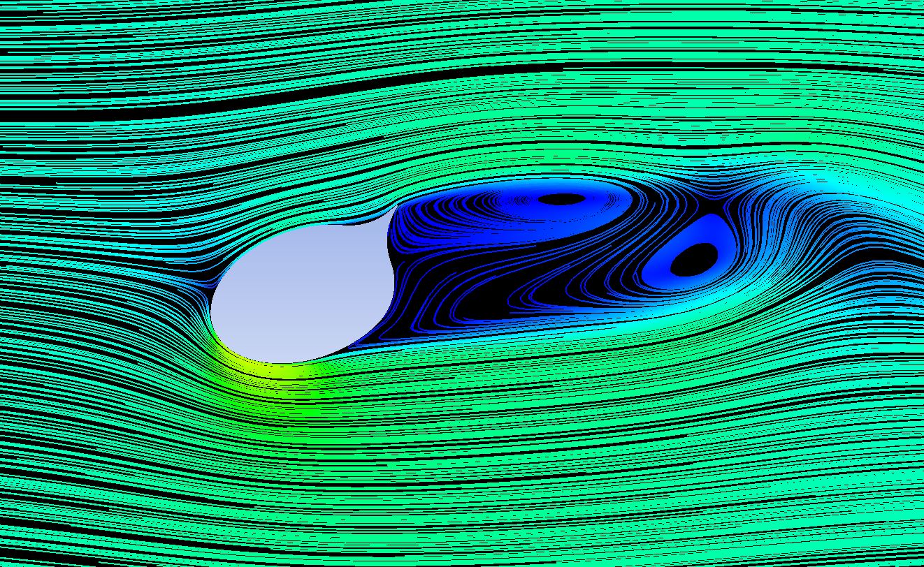
A cylindroid geometry generates alternating vortices on the leeward surface, producing a wake that produces alternating forces on the geometry. As soon as suction begins, the flow adheres, increasing the velocity on the underside of the sail, lowering its pressure according to Bernoulli’s theorem. The integral of these negative pressures on the surface raises the lift coefficient, and therefore the sail impulse. In addition, the latter aerodynamic configuration, with an aerodynamic balance without alternating vortices, produces constant lift forces along the time.
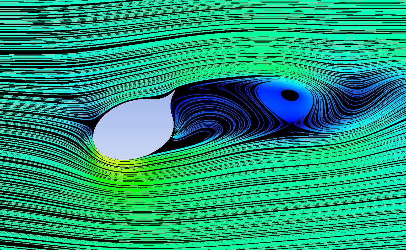
The integral of these negative pressures on the surface raises the lift coefficient, and thus the sail propulsion. In addition, this last aerodynamic configuration, with an aerodynamic equilibrium without alternating vortices, produces constant lift forces along the time.
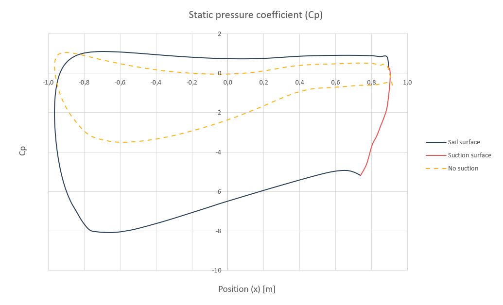
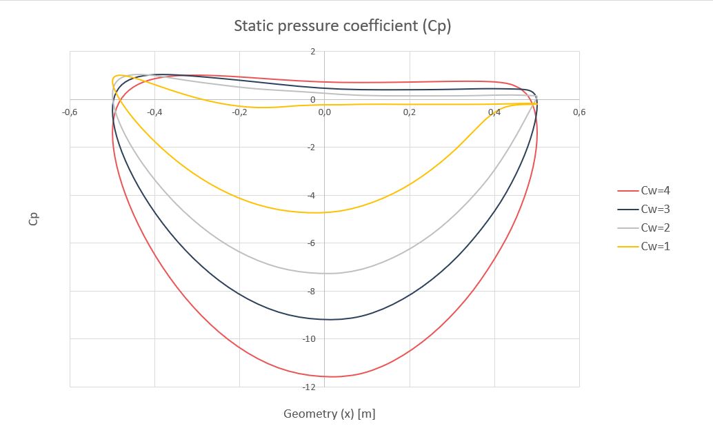
The following graph shows the dimensionless coefficient of static pressure ( C_p ) on the sail geometry at the point of flow adhesion.
C_p = \Large \frac{p}{\frac{1}{2} \rho V^2}
Where:
- p : static pressure on the sail surface.
- \rho : wind density
- V : wind speed
According to the previous paragraph, integral of the pressure coefficient curves ( C_p ) provide us with the lift coefficients ( C_l ). As it can be observed, the pressure curves with suction generate integrals, or areas under the curve, of higher values than the pressure curves without suction. This is the base of the principle of operation for the suction sail or Cousteau’s turbosail.
Variation of the design parameters
The characteristic length ( L_c ) and sail height ( H ) are two parameters that once the sail is manufactured do not change, they are fixed parameters by design. An increase or decrease in these parameters is directly proportional to an increase or decrease in the flow rate required to adhere the flow and directly proportional to the lift force generated.
The flow (wind) speed ( V ) is a variable parameter. If the wind speed increases, the suction flow rate to maintain the minimum adhesion point must also increase proportionally, otherwise the flow is separated and the lift coefficient drops drastically. The lift force depends quadratically on the flow velocity, so that, if adhesion is achieved, the lift is increased very significantly.
The key to turbosail operation is the conditional statement “if flow adhesion is achieved”.
Having fixed the maximum flow rate and pressures of the suction fan by design, together with the parameters mentioned above, characteristic length ( L_c ) and sail height ( H ) there is a maximum wind speed ( V_{max} ) above which, the turboprop is unable to adhere the flow, since it is not able to generate the suction flow rate at the pressure required for it.
Pressure loss and power
An essential factor that determines the power of the suction fan is the pressure loss. In a turbosail, there are three main pressure losses to consider:
In our handbook Pressure drop in perforated thin plates, this energy loss can be approximated according to the parameters involved in this calculation.
The hydraulic power ( W_h ) required to adhere the flow can be determined by:
W_h = | p | · Q
where Q is the flow rate necessary for the flow adherence, assumed constant in each section of the suction surface, and p is the pressure necessary at the suction fan inlet, which can be expressed as:
p = p_{ext} - \Delta p_{asp} - \Delta p_{dir} - \Delta p_h
With p_{ext} as the pressure outside the suction surface and is always negative.
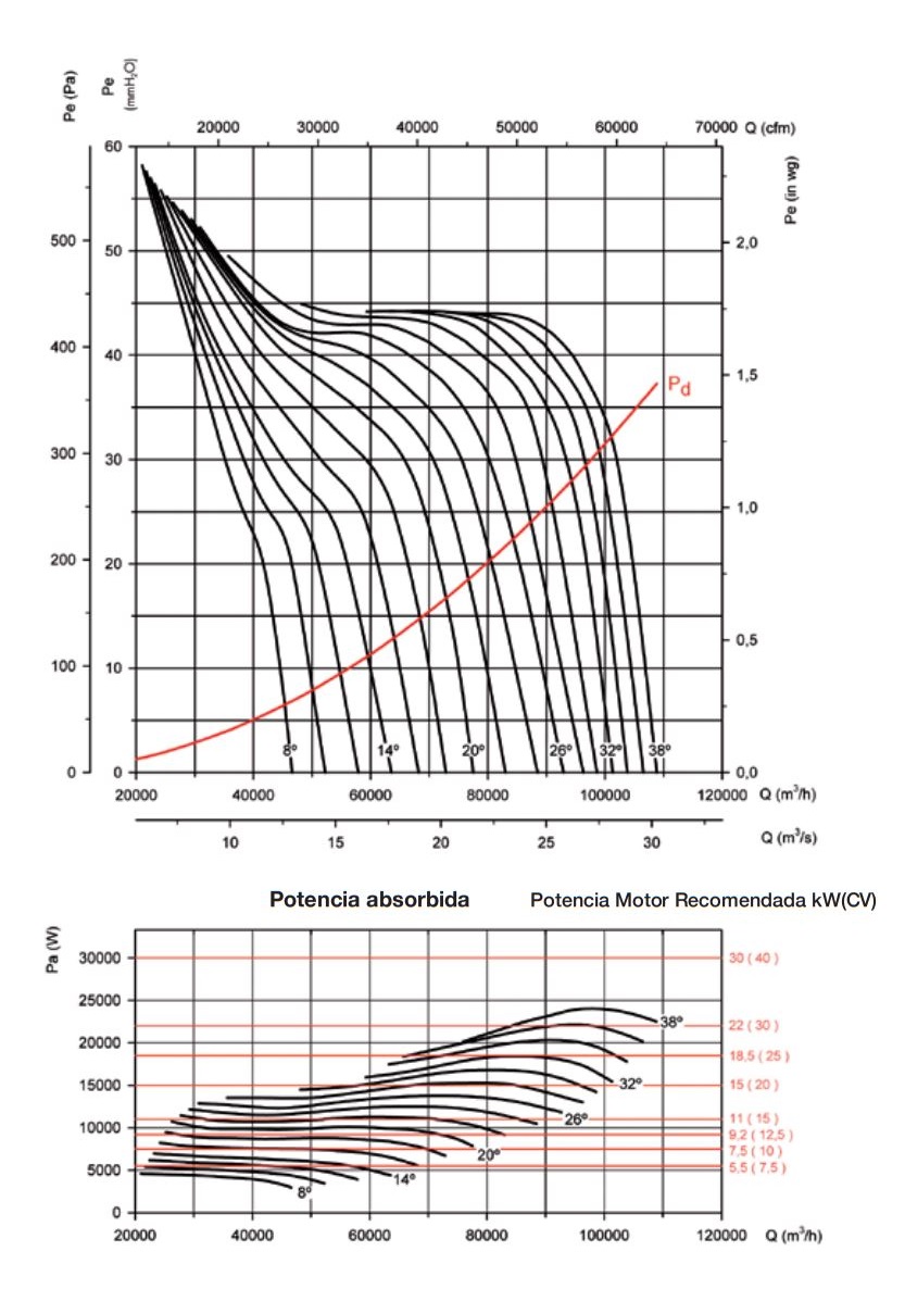
Since the fan is driven by an electric motor there is a performance efficiency when converting from hydraulic power ( W_h ) to electric power ( W_e ), so fan manufacturers provide the ratio between pressure and flow with the electric power supplied by each specific fan.
Rotorsail
In 1853, Heinrich Gustav Magnus, German physicist and chemist, identified the effect that bears his name through the rotation of objects within a moving fluid, where the tangential or peripheral velocity of the object is added or subtracted from that of the fluid depending on the point of the object being analyzed, creating a rotational flow around the body and producing a lift force.
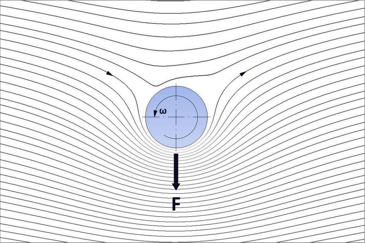
Therefore, to produce a lift force ( F_l ), with its corresponding lift coefficient ( C_l ), the cylindrical column section must be rotated at a significant velocity ( \omega ) and adimensionalized through the tangential or peripheral velocity coefficient ( C_{\omega} ):
C_{\omega} = \Large \frac{\omega L_c}{2 V}
C_l = \Large \frac{F_l}{\frac{1}{2}\rho V^2}
Where:
- C_{\omega} : tangential velocity coefficient
- L_c : characteristic length coincident with the sail diameter
- \omega : angular speed
- V : wind flow speed
- C_l : lift coefficient
- \rho : fluid density
- F_l : lift force
En los años 20 del siglo pasado, Anton Flettner asistido por el ingeniero Ludwig Pandtl, entre otros, inventa el rotor que lleva su nombre para la impulsión de embarcaciones. Las velas de rotor o rotores Flettner aprovechan el efecto Magnus para adherir el flujo a una sección perfectamente cilíndrica en rotación.
Ludwig Prandtl
(Freising, 1875 – Göttingen, 1953)
German engineer and physicist, specializing in the theory of aerodynamics, fluid mechanics and the mechanical performance of materials, developed the mathematical foundation that supports the fundamental principles of subsonic aerodynamics. Prandtl’s number, which relates kinematic viscosity to thermal diffusivity in the analysis of fluid mechanics, has been named in his honor.
The following video shows the adhesion of the flow in the circular section of the rotor by means of the rotation of the rotor. It is, therefore, a very different mechanism when it comes to adhering the flow if we compare it with suction sails.
In 1923, the Aerodynamics Research Institute (AVA) in Göttingen experimentally determined the drag ( C_d ) and lift ( C_l ) coefficients of the rotor as a function of constant inlet flow velocities, which constitute the basis for the calculations of such systems. These studies were extended in 1985 by ISF Hamburg, with new wind tunnel tests to characterize rotor ends with discs of various diameters, in addition to reaffirming the existing coefficients.
The graph of these lift coefficients ( C_l ) with respect to the tangential velocity coefficient ( C_{\omega} ) is shown below.
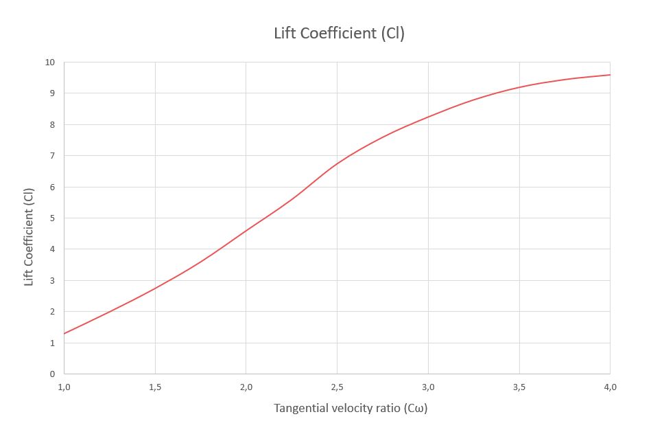
According to the results, the optimal rotor performance is achieved when the tangential velocity coefficient reaches the value of 4, at which point the configuration of static pressures on the sail geometry becomes symmetrical.
Similarly, the aspect coefficient ( \large \frac{H}{L_c} ) must also be higher than this value to obtain high ratios between the lift and drag coefficient (ε). At present, this value is around 7.
Disks of a certain size at the ends of the sail also allow to improve the three-dimensional performance, raising the coefficients.
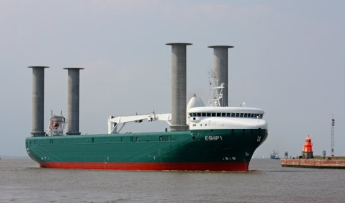
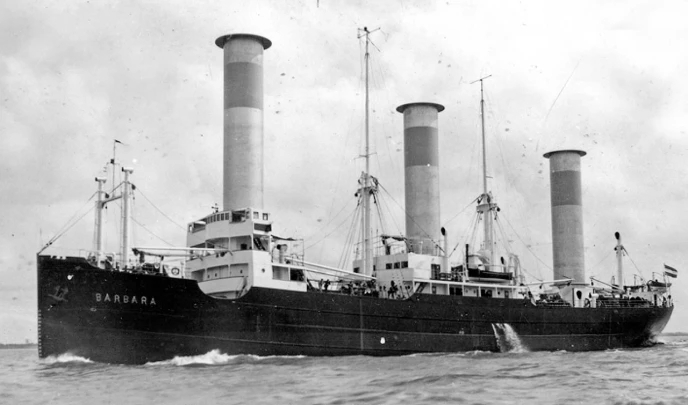
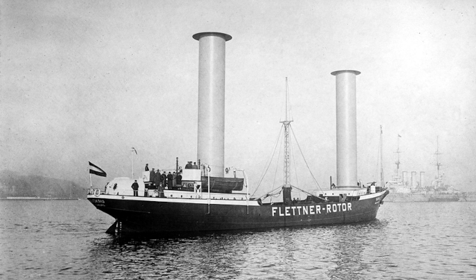
Thus, ships such as the Buckau or the RMS Barbara were adapted with these rotors during the 1920s with very satisfactory propulsion results. Today, the E-ship is a cargo RoLo that is propelled with the help of this technology. We compare some of their characteristics:
| Buckau | RMS Barbara | E-ship | |
|---|---|---|---|
| Nº rotors | 2 | 10 | 4 |
| Diameter [m] | 2.8 | 4 | 4 |
| Height [m] | 16 | 17 | 27 |
| Angular speed [rpm] | 125 | 160 | 300 |
| Power/rotor [kW] | 10 | 30 | 100 |
| Ship length [m] | 45 | 85 | 130 |
Families of rotors
Since the rotation drives have to move the entire sail, the rotational speed ( \omega ) is limited mainly by the inertial forces reached in the cylindrical geometry.
Below is a table with approximate values of the maximum rotational speeds ( \omega_{max} ) depending on the diameter or characteristic length ( L_c ) of the sail:
| Lc [m] | ω [rpm] |
|---|---|
| 2 | 450 |
| 3 | 300 |
| 4 | 225 |
| 5 | 180 |
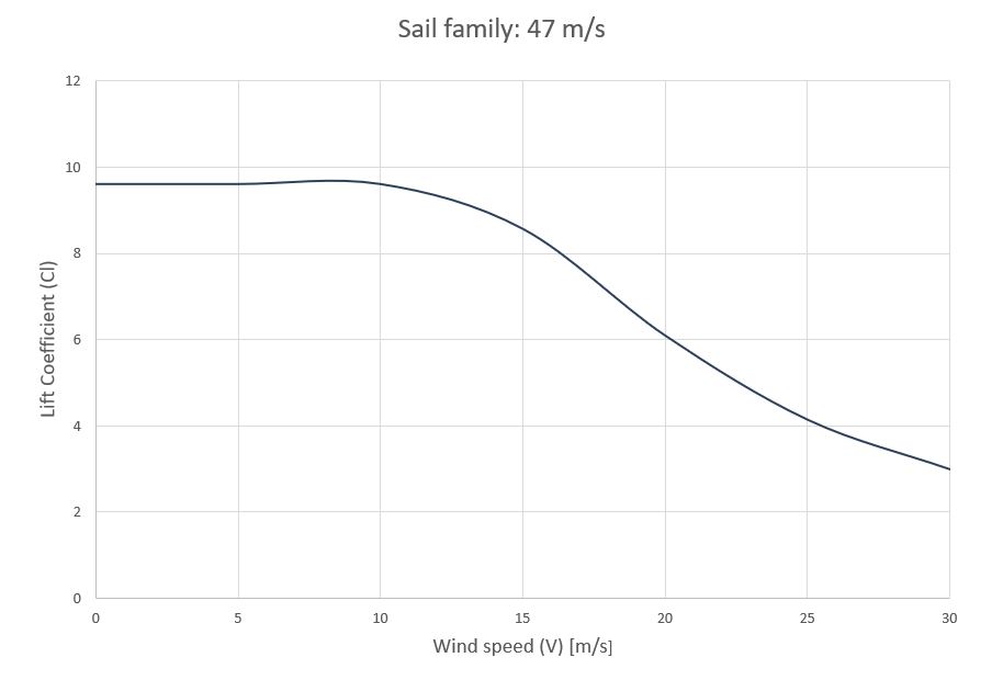
According to these values, for high wind speeds, the tangential velocity coefficient will not always be able to reach the optimal value of 4, so the lift coefficients will be below the maximum (9.6).
From the tangential velocity coefficient ( C_{\omega} ) it can be deduced that rotors having the same tangential velocity ( V_t ) perform in the same way with respect to the magnitude of the fluid velocity ( V ).
V_t = \Large \frac{1}{2} \normalsize \omega_{max} L_c
These are the so-called rotor families. When these increase in size ( Lc ), they conserve their behavior and aerodynamic coefficients while decreasing the maximum rotational speed ( \omega_{max} ).
The following graph shows the decrease of the lift coefficient ( C_l ) with respect to the wind speed ( V ) for the family 47m/s.
Turbo vs. Rotor
Below is a graph comparing the lift forces for a turbosail, whose maximum flow speed is 15m/s, and a rotor sail, both with a characteristic length of 2m and a height of 10.2m (Cousteau’s Alcyone configuration).
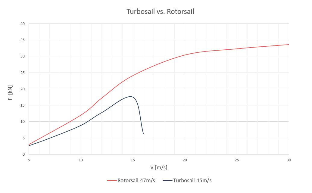
\lambda = \Large \frac{H}{L_c}
Summary
In summary, the suction sails seem to be limited in size to a geometry similar to that of the Alcyone, so they are not capable of generating the large propulsion required by large vessels over 40 meters length.
Rotorsails prove to be more versatile than suction sails covering a fairly wide range of propulsion forces. Whereas for short ships both could enter into competition at wind speeds below 10-15 m/s, suction sails cannot even overshadow them in propelling large vessels, mainly due to their technical inefficiency in adhering the flow to achieve significant lift.
Related posts
Projects


About us