The relevance of stiffness in solar trackers
There is a tendency to think that the damping (ξ) is a critical value at the time of an aeroelastic analysis of a single-axis tracker, and this statement is true especially in the performance against galloping, but the relevance of stiffness in single-axis solar trackers is so great that any other parameter compared to it seems insignificant.
If we analyze this statement qualitatively, highly stiff structures remain static, without considerable strain, facing the wind acting on them, so the inclusion of damping would not make sense since there is no motion to attenuate.
There is no infinitely stiff structure, so engineering must consider whether the movements produced by the wind can be considered within the static calculation or, on the other hand, a dynamic analysis must be made, as in the case of single-axis solar trackers with a central drive system.
Torsional stiffness of a tracker can be considered to be given entirely by its torque tubes without making significant errors in calculation. If we assume that the wind acts on the tracker as a moment distributed along each torque tube, we have that:
- The maximum angle of twist ( \phi_{max} ) is in the farthest section from the drive system and depends on the following parameters:
\phi_{max} = \Large \frac{m L^2}{2GJ}
Where:
-
- \phi_{max} : maximum angle of twist in radians
- m: moment distributed along the length of the torque tube
- L: torque tube length
- G: shear modulus of material
- J: torsion constant for the section
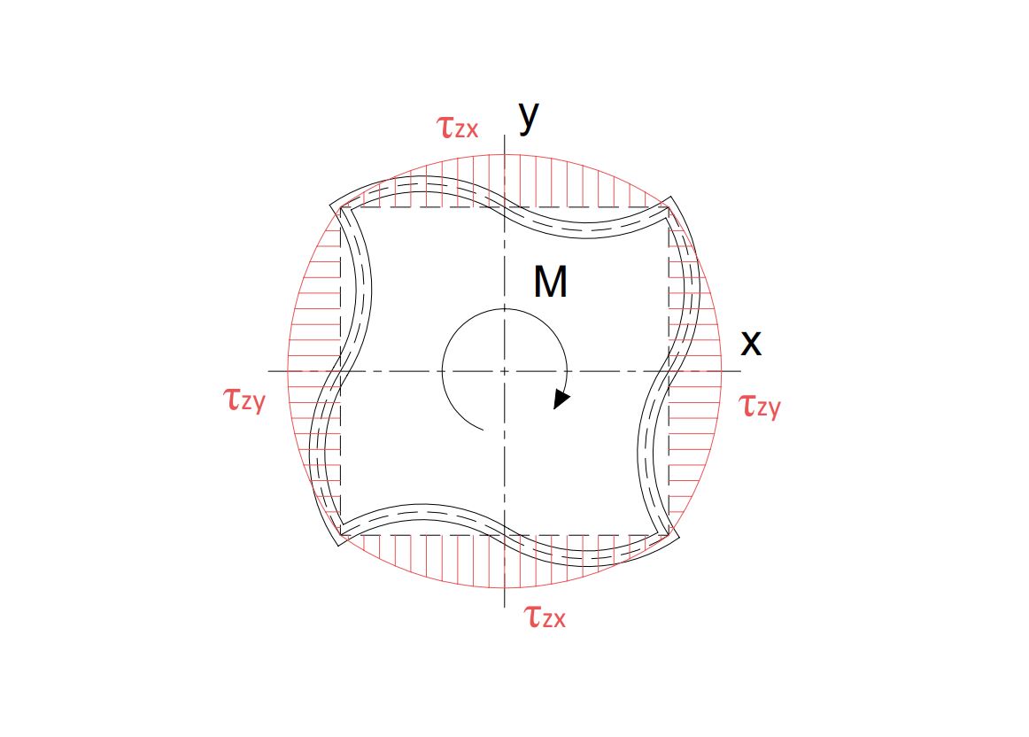
- The maximum shear stress due to torsion ( \tau_{max} ) is found in the section closest to the drive system. In a thin-walled square section, the tangential stress is zero at the vertices of the square and maximum at half of the sides.
\tau_{max} = \Large \frac{m L}{2eA_m}
Where:
- \tau_{max} : maximum tangential stress by torsion.
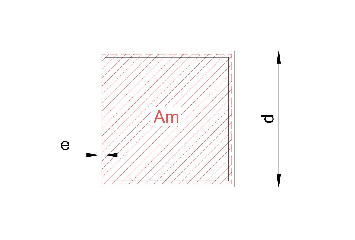
- e : torque tube wall thickness
- A_m : area enclosed by the midline of the torque tube wall
Solid circular is the best cross-section to support torsion, but it is not used in this type of structures due to its high cost. The next candidate is the thin-walled circular profile, although it is used in some trackers, the hollow square profile is preferred because having four planes facilitates the assembly of elements on it.
The torsion constant of the section (J) for a thin-walled square profile has the expression given by Bredt’s formula:
J = e(d-e)^3
Where e and d are the thickness of the wall and the outer side of the torque tube respectively.
On the other hand, the area enclosing the midline of the section thickness ( A_m ) is:
A_m = (d-e)^3
Writing again the expressions of maximum stress and twist for each torque tube, we have that:
\phi_{max} = \Large \frac{m L^2}{2Ge(d-e)^3}
\tau_{max} = \Large \frac{m L}{2e(d-e)^2}
Both expressions are related through the distributed moments as follows:
\Large \frac{\tau_{max}}{\phi_{max}} \normalsize = \Large \frac{G(d-e)}{L}
It is also possible to deduce a distributed stiffness (k) that will be very useful in the two-dimensional CFD computational calculation.
k = \Large \frac{m}{\phi} \normalsize = \Large \frac{2Ge(d-e)^3}{L^2}
Based on these simple formulas, it is possible to calculate the maximum admissible distributed moment for a section of a given geometry and a given length, as well as the maximum deflection for these moments.
Three quarters of the permissible yield limit ( f_y ) of the material (S355JR steel) has been taken as there are other stresses, like bending and shear, to be considered in the torque tube:
\Large \frac{3}{4} \normalsize f_y > \sigma_{VM} = \sqrt{3} \tau_{max} = \sqrt{3} \Large \frac{mL}{2e(d-e)^2}
With \sigma_{VM} as the Von Mises stress, and from which the maximum distributed moment can be written as:
m < \Large \frac{2e(d-e)^2}{\sqrt{3}L} \frac{3}{4} \normalsize f_y
The following are the admissible distributed moments for torque tubes with the specified lengths and cross-sections:
| Section | m max [Nm/m] | |||
|---|---|---|---|---|
| #140.5 | 2666 | 1439 | 1083 | 869 |
| #210.5 | 6146 | 3319 | 2498 | 2003 |
| #250.5 | 8779 | 4741 | 3568 | 2861 |
| #300.5 | 12728 | 6873 | 5173 | 4147 |
| L [m] | 9.5 | 17.5 | 23.3 | 29.1 |
For these maximum moments, the maximum twists of the last section are shown below.
| Section | ф max [º] | |||
|---|---|---|---|---|
| #140.5 | 6.90 | 12.77 | 16.97 | 21.17 |
| #210.5 | 4.54 | 8.41 | 11.18 | 13.94 |
| #250.5 | 3.80 | 7.04 | 9.35 | 11.66 |
| #300.5 | 3.16 | 5.85 | 7.77 | 9.69 |
| L [m] | 9.5 | 17.5 | 23.3 | 29.1 |
If distributed moments on the tracker calculated by CFD analyses or wind tunnel tests is higher than those admitted by our torque tube marked in the table above, the tube will collapse due to torsional tangential stresses.
Stiffness vs Torsional divergence
In our post about divergence in solar trackers a minimum stiffness ( = [latex] k_{div} ) is necessary to avoid torsional divergence before reaching the plant survival wind speed V_{surv,1h} = U = 30m/s:
k_{div} = \Large \frac{1}{2} \normalsize \rho U^2 b^2 \Large \frac {\partial C_m}{\partial \alpha}
Therefore, the stiffness in single-axis solar trackers, defined by the torque tube geometry, must be greater than this limit.
\Large \frac{2GJ}{L^2} \normalsize > \Large \frac{1}{2} \normalsize \rho U^2 b^2 \Large \frac {\partial C_m}{\partial \alpha}
| Section | k div30 | k [Nm/m rad] | |||
|---|---|---|---|---|---|
| #140.5 | 19087 | 22140 | 6456 | 3657 | 2351 |
| #210.5 | 19666 | 77525 | 22605 | 12806 | 8231 |
| #250.5 | 20001 | 132336 | 38587 | 21860 | 14051 |
| #300.5 | 20423 | 231018 | 67360 | 38162 | 24529 |
| L [m] | 9.5 | 17.5 | 23.3 | 29.1 | |
Values marked in red indicate a stiffness lower than that required to avoid torsional divergence for the marked tube cross-section and length.
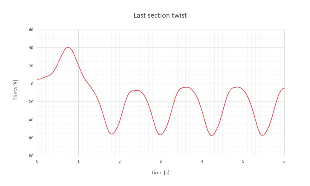
The following is an example of the moments calculated for a single-axis tracker whose torque tubes measure 17.5m, 30 modules on each side of the central drive system in two rows of 15, with a cross-section #140.5, working with the plant survival wind speed ( V_{surv,1h} = 30m/s ) with a damping coefficient of 0.25.
According to the tables, the torque tube stiffness would not meet the stiffness required to save the torsional divergence, but also the distributed moments reached in the section would exceed the yield limit of the material, so this tube would collapse under dynamic loads of the survival wind, and may or may not couple with aeroelastic phenomena of torsional divergence, depending on the wind speed.
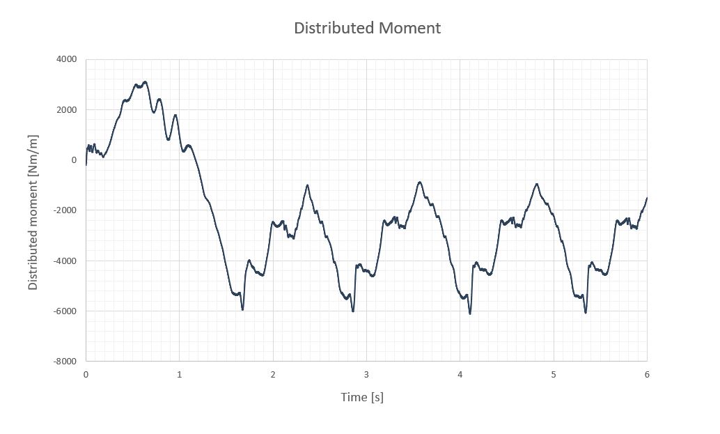
In this case, the video would not be realistic since the torque tube would collapse when the maximum admissible distributed moments are reached, but if we did not have this limitation in the material, the tracker would twist at large angles when facing such loads since its stiffness is small compared to the energy of the plant survival wind speed ( V_{surv,1h} =30m/s ).
Related posts
Projects


About us