Damping for solar trackers
In the posts of Atreydes Engineering, we have remarked the importance of damping for solar trackers (ξ) which allows delaying, mitigating or eliminating aeroelastic phenomena in the design of single-axis solar trackers.
Here, the physical dampers required for this purpose will be defined according to the results of the equations to prevent torsional galloping and the performance of vortex shedding analysis to avoid resonance or at least excessive vibration introducing high stresses in the tracker components under design wind speeds.
According to these premises and the tracker geometry defined in the posts for torsional galloping calculation and vortex shedding analysis, the damping coefficient necessary to guarantee the stability throughout the plant life has an approximate value of 0.25.
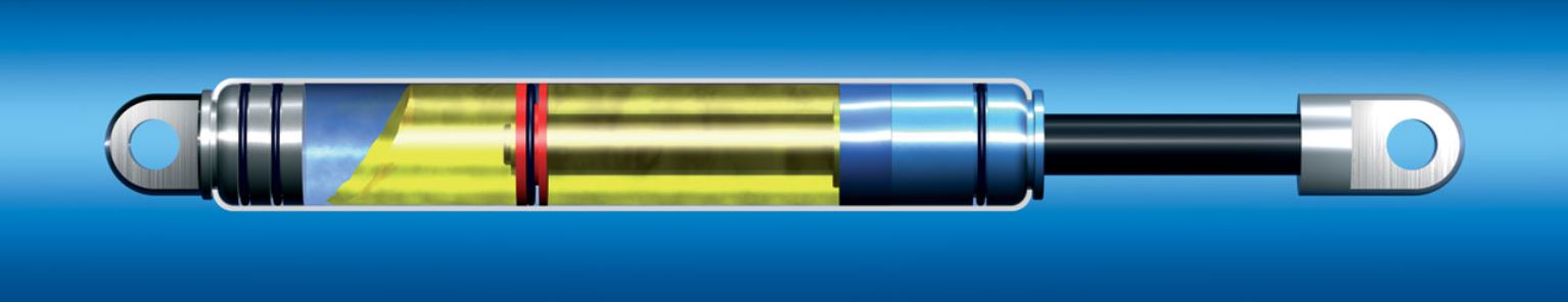
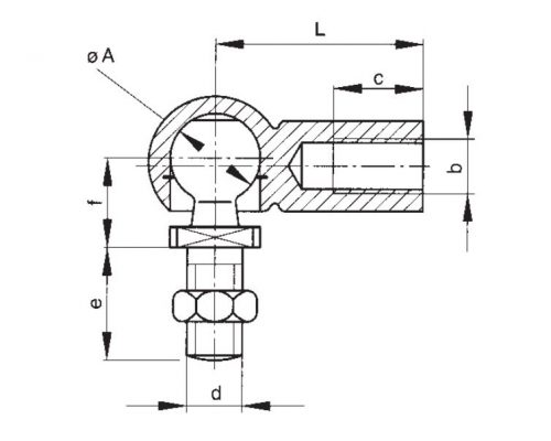
Since tracker structures cannot provide this damping by itself, linear dampers will therefore make this functionality, as they are cheap and easy to install components.
Geometry
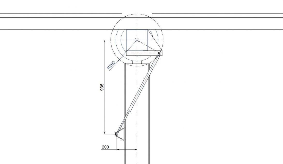
It is important to remember that a tracker needs torsional damping which must be provided by linear dampers. For this reason, the position of the damper is not trivial with respect to the tracker rotation axis, as some geometrical requirements have to be met:
The lever arm is a very important parameter because it expresses the amount of rotation produced per damper advance unit. The higher the lever arm (d), the better the damper performance with respect to the tracker, since it will provide a better response to its rotation with the lowest possible force.
Thus, a relation can be established between the variation of the tracker rotation angle (Δθ) and the variation of the damper extension (Δx):
\Delta \theta \approx \Large \frac{\Delta x}{d}
Where d is the lever arm.
Deriving the expression with respect to time, we have that:
\dot \theta \approx \Large \frac{\dot x}{d}
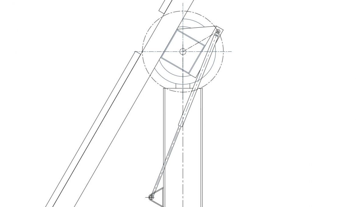
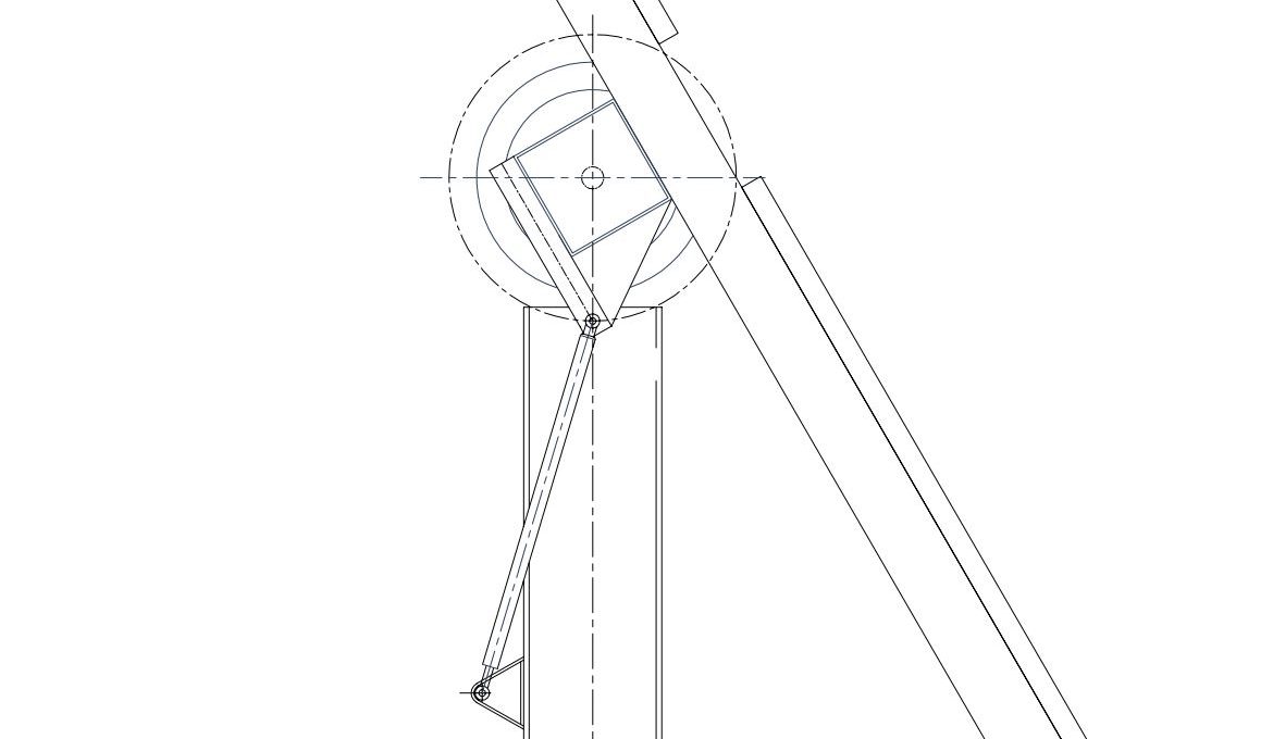
For the configuration defined in the images above, the variation of the lever arm with respect to tracker tilts is shown graphically.
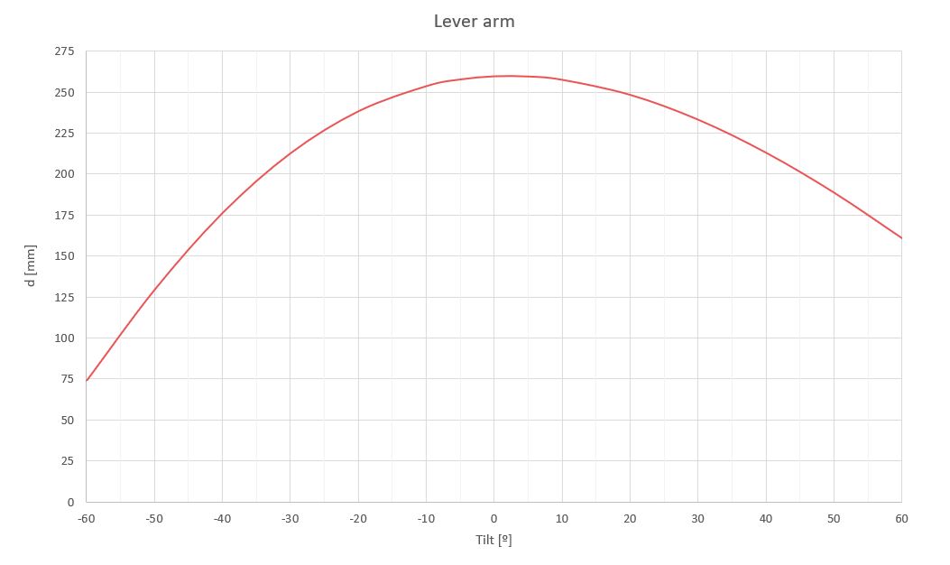
It is necessary to clarify that it is preferable that the largest lever arm coincides with the tracker stow position since this tilt will support the highest design loads and moments, corresponding to survival wind speed of the plant (Vsurv).
Calculation
According to the equations defined in our post Solar Flutterintg, damping on solar trackers ( \hat c_\theta ) needed to define our linear dampers is:
\xi = \Large \frac{\hat c_\theta}{2\hat I \omega_n}
Aisolating, we have that:
\hat c_{\theta} = 2 \xi \hat I \omega_n = 4 \pi \hat I n
Where:
- \hat c_\theta : three-dimensional angular damping of the system.
- \xi : damping coefficient. 0.25.
- \hat I : three-dimensional inertia involved in the vibration mode. 800kgm².
- n : natural frequency of the system. 2.1Hz.
With these values we need a total three-dimensional damping ( \hat c_\theta ) of 5348 Ns/rad, which should be distributed linearly across the entire tracker.
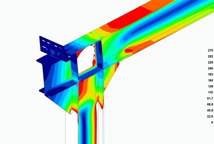
Linear dampers need a fixed point to transmit the load generated by the tracker rotational speed, so it is only possible to damp the tracker under its pillars, which will be used to transmit the load. So, each outer pillar will have a linear damper.
Excluding the central pillar which supports the drive system, each 17.3m torque tube is supported by 3 outer pillars spaced 5.8m apart, so each linear damper should provide a rotational damping (ci) of 1783Ns/rad.
c_{\theta i} = \Large \frac{\hat c_\theta}{nº pillars} \normalsize = 1783Ns/rad
The damping constant ( c_{\theta i} ) is angular, so we will have to divide by the lever arm of the stow position ( d_{stow} ) to obtain the linear constant of our dampers. The stow position is taken as a reference because this will be the position where the dampers make the most work to stabilize, on the one hand, the higher tracker loads at the plant survival wind speed and, on the other hand, to avoid the occurrence of torsional galloping.
c_{xi} = \Large \frac{\hat c_{\theta i}}{d_{stow}} \normalsize = 6858Ns/rad
This parameter indicates that the damper has to transmit a load of 6880N for each meter per second that the tracker pushes or pulls it. It is also the reason why the amplitude of a harmonic vibration in the tracker is not so high and decreases along the time.
Since the damping constant is difficult to determine, dampers are cataloged by the force they transmit.
For our calculations, the maximum angular speeds are a result of CFD analyses. According to them, this maximum angular speed is found in the case of stow position at plant survival speed.
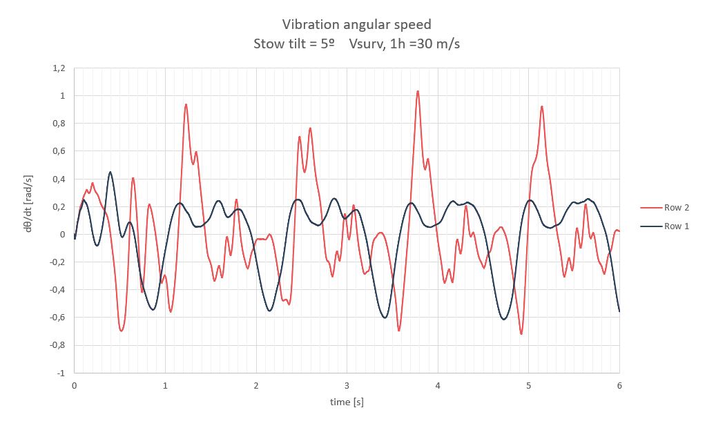
For practical purposes, we can consider a maximum speed of ±1rad/s, so the maximum tensile and compressive force to be transmitted by the linear damper is:
F = c_{xi} \dot x = c_{\theta i} \Large \frac{\dot \theta}{d_{stow}} \normalsize = 1783 \Large \frac{1}{0.26} \normalsize = 6858N
Other considerations
The following are a series of requirements to be considered in damping for solar trackers:
Related posts

Projects


About us