Do single-axis trackers dream of “galloping” sheep?
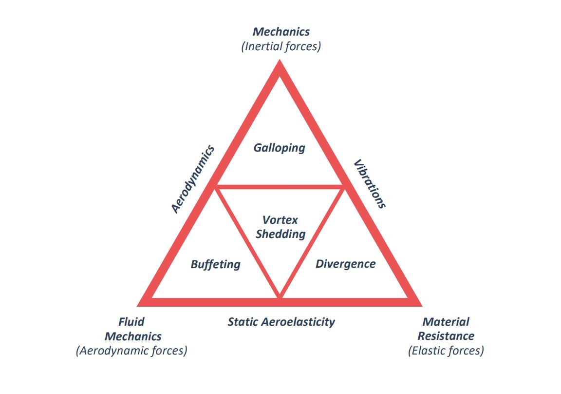
In our post Fluttering on single-axis solar trackers, we introduce the 4 aeroelastic instability phenomena. Of all of them, torsional galloping is the one that has the highest tendency to appear in single-axis solar tracker plants, especially in the perimeter rows which face the clean wind flow, without being modified by other structures, as is the case of trackers inside the plant, in which the trackers of the previous row modify the wind incident on them (wake buffeting).
Torsional galloping is an aeroelastic phenomenon that was first observed in the airplane wings at high flight speeds. It appears at a certain speed and, unless this speed is reduced, the phenomenon does not disappear. This instability can be explained mathematically through a translation and rotation of the wing section, so we would have a translational and a torsional galloping which are coupled. In single-axis solar trackers, since the vertical component is restricted by the pillar supports, only the torsional component arises, given that this degree of freedom is more flexible than the translational one.
Galloping on single-axis solar trackers appears at the wind speed at which the aerodynamic forces nullify and turn negative the system damping, amplifying the position of the system along the time:
U_{cr}|_{gal} \geq \Large \frac {-4 I_{\theta} \omega_n \xi} {\rho b_c^2 r \frac{\partial c_m}{\partial \alpha}}
Although this mathematical model, based on the reduction of aerodynamic loads at a single point of the tracker, is too simplistic to fully explain this phenomenon, it serves to qualitatively calculate the critical velocity in a two-dimensional model of the tracker section and helps to understand the parameters on which galloping depends.
Knowing that \Large \frac{\partial c_m}{\partial \alpha} has to be negative to obtain a physically positive wind speed, we can transform this formula to the one proposed in Eurocode 1: Actions on structures. Wind actions.
For this, knowing that:
\omega_n = 2 \pi n
Where \omega_n is the angular frequency and n is the system natural frequency.
\delta = \Large \frac {2 \pi \xi} {\sqrt {1-\xi^2}} \normalsize \simeq 2 \pi \xi
For low damping coefficients, where \delta is the logarithmic decrement.
Defining the Scruton number (Sc), which relates the inertia of the structure to that of the air which displaces when vibrating, affecting it by damping expressed by logarithmic decrement:
Sc = \Large \frac {2 I_{\theta} \delta} {\rho b^2}
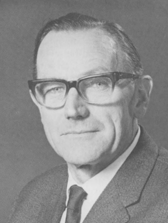
Christopher “Kit” Scruton
(Shipley, 1911 – Havant, 1990)
He is remembered for his pioneering work on wind engineering and industrial aerodynamics. However, it is worth noting that for nearly half his career he worked on aircraft flutter and it is this scientific base that provided the fundamental techniques for analysis of the dynamic response of bridges, buildings and structures to wind.
And considering that:
-r \Large \frac{\partial c_m}{\partial \alpha} \normalsize = \Large \frac {a_G} {b}
We obtain the formula for the critical speed of torsional galloping onset proposed by Eurocode:
U_{cr}|_{gal} \geq \Large \frac {2 Sc n b} {a_G}
aG is the factor of galloping instability, which must be calculated experimentally through aeroelastic wind tunnels. However, the standard says that, if is not known, to take the value of 10, to be on the safe side. It also proposes values for different sections ranging from 0.4 to 7.5, but given the morphology of the tracker section, none conforms to it, being aG higher the higher aspect ratio of the section (d/t), in the standard d/b.
Aspect ratio is defined as the longitudinal dimension to the wind (d) divided by the transversal dimension (t).
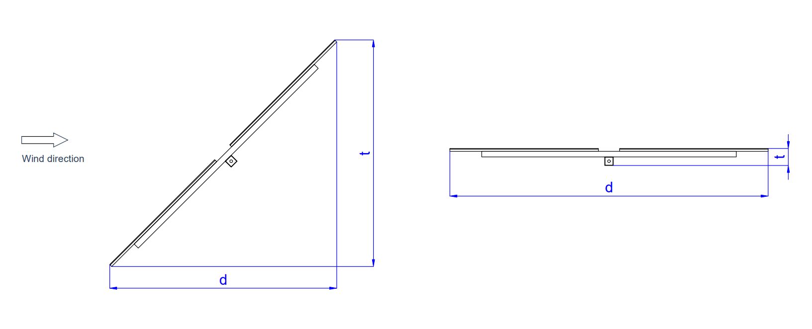
Tilted trackers have a smaller aspect ratio with respect to their horizontal position, so they retard the torsional galloping critical speed. This is why recently a slight pitching of trackers in their stow position is being adopted, provided that static loads allow it.
Eurocode also proposes values for the logarithmic decrement for steel structures, where the typical values are around 0.05 which is equivalent, through the formula \delta \simeq 2 \pi \xi , to a damping coefficient of 0.01.
Returning to the critical speed formulation, this time defined through fundamental parameters, we have that:
U_{cr, 1h,10m} \geq \Large \frac {2 Sc n b} {a_G} \normalsize = \Large \frac {4 I_{\theta} n \delta} {\rho b a_G} \normalsize = \Large \frac {8 \pi I_{\theta} n \xi} {\rho b a_G}
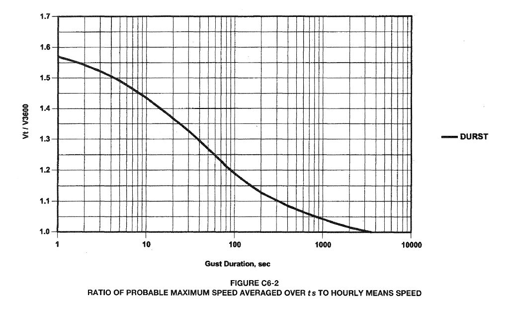
For a photovoltaic plant, the torsional galloping wind speed must be higher than the plant survival speed defined in the specifications. This survival speed is usually around U_{sur, 3s,10m} = 50m/s . Knowing that \Large \frac {U_{sur, 3s,10m}}{U_{sur, 1h,10m}} \normalsize = 1.52 , through the graph relating wind speeds measured at different time windows, we have that:
U_{sur, 1h,10m} = \Large \frac{U_{sur, 3s,10m}}{1.52} \normalsize = \Large \frac{50}{1.52} \normalsize \geq \Large \frac {8 \pi I_{\theta} n \xi} {\rho b a_G}
Knowing the survival speed and that the galloping critical velocity must be higher than this, a linear relation can be established between the damping coefficient required for a given value of aG. Since we do not know this parameter without an aeroelastic wind tunnel test, but we know its approximate range of values that can take [0,10], for a standard tracker of 17.3m and 30 modules in two rows per torque tube, whose main two-dimensional parameters are:
I = 100kg/m²
n = 1.24 Hz
b = 4.7m
We can establish a graph of values with the following equation:
\xi = 0.0608 a_G
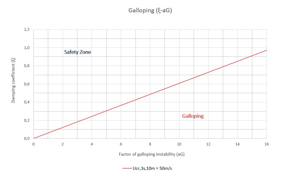
With these values, it can be verified that the system damping coefficient, defined approximately by the Eurocode recommendations at 0.01, is far below the one necessary to avoid the appearance of galloping on single-axis solar trackers before the plant survival wind speed, so the plant will inevitably operate with this risk that will end up materializing with a high probability, affecting mainly the windward perimeter trackers.
Due to the distance of the system damping from that needed to avoid torsional galloping for a given survival speed, it is strictly necessary to install physical dampers or shock absorber to increase this value. In our post Damping design for single-axis solar trackers, we describe the main parameters to consider when designing these systems.
Torsional galloping is the first instability to be quantified and eliminated from the four aeroelastic phenomena mentioned above, since it is more likely to appear than the others. The physical damping systems designed to avoid this occurrence will have a very positive influence on the phenomena of vortex shedding and buffeting, reducing the amplitudes of their oscillations. However, this damping will not affect the torsional divergence which strictly depends on the sytem stiffness.
Related posts

Projects


About us